INSTALLATION
Power Wiring Interconnections
All wiring must be the proper size, properly supported, of approved insulation qualities, and protected by NEC approved conduit.
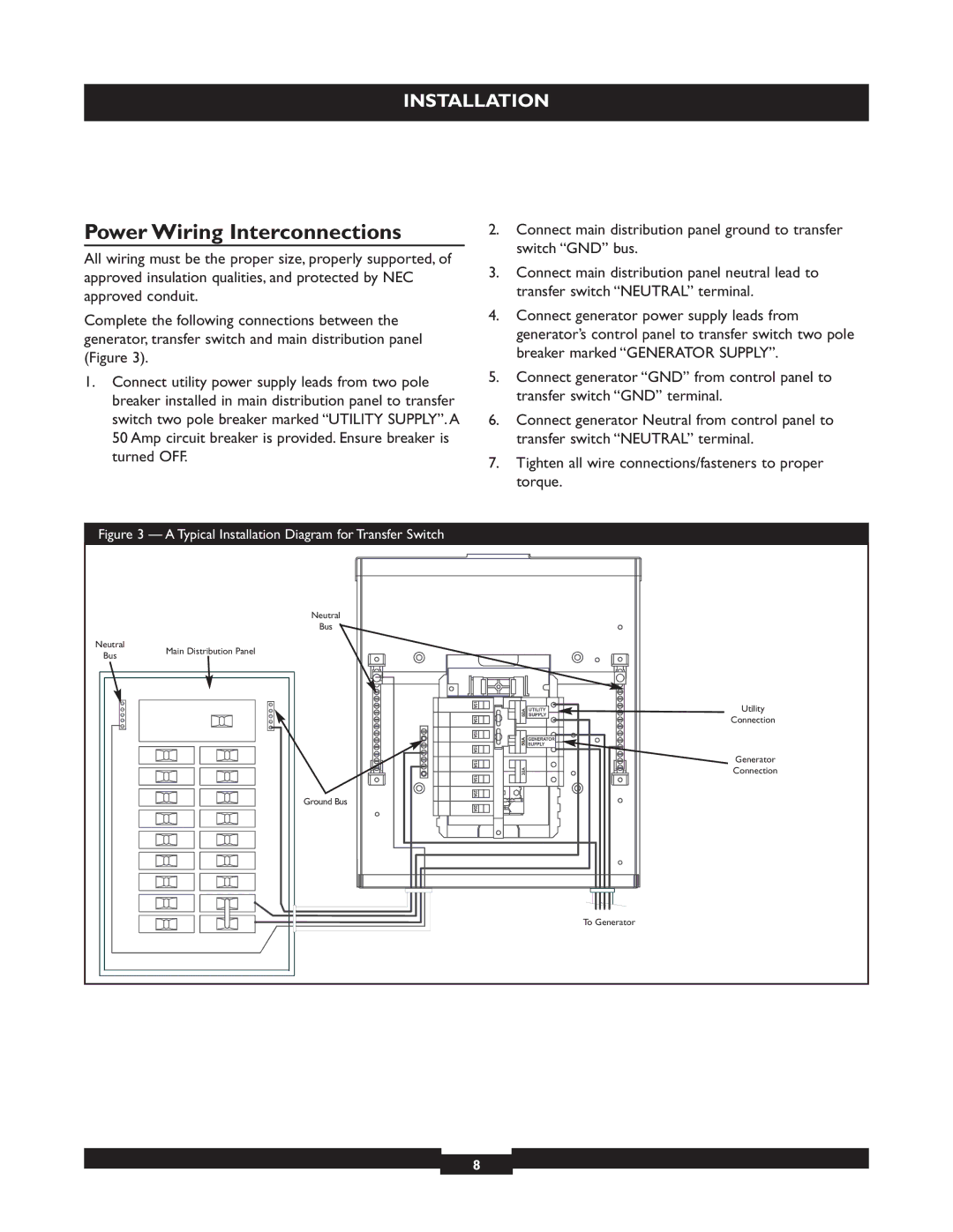
Complete the following connections between the generator, transfer switch and main distribution panel (Figure 3).
1.Connect utility power supply leads from two pole breaker installed in main distribution panel to transfer switch two pole breaker marked “UTILITY SUPPLY”. A 50 Amp circuit breaker is provided. Ensure breaker is turned OFF.
2.Connect main distribution panel ground to transfer switch “GND” bus.
3.Connect main distribution panel neutral lead to transfer switch “NEUTRAL” terminal.
4.Connect generator power supply leads from generator’s control panel to transfer switch two pole breaker marked “GENERATOR SUPPLY”.
5.Connect generator “GND” from control panel to transfer switch “GND” terminal.
6.Connect generator Neutral from control panel to transfer switch “NEUTRAL” terminal.
7.Tighten all wire connections/fasteners to proper torque.
Figure 3 — A Typical Installation Diagram for Transfer Switch
| Neutral | |
| Bus | |
Neutral | Main Distribution Panel | |
Bus | ||
| ||
| Utility | |
| Connection | |
| Generator | |
| Connection | |
| Ground Bus | |
| To Generator |
8