Assembly Instructions
A. Assembly
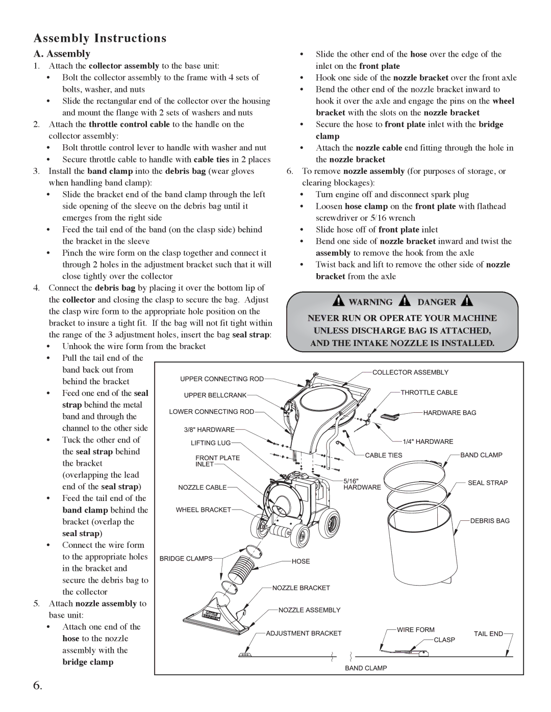
1.Attach the collector assembly to the base unit:
•Bolt the collector assembly to the frame with 4 sets of bolts, washer, and nuts
•Slide the rectangular end of the collector over the housing and mount the flange with 2 sets of washers and nuts
2.Attach the throttle control cable to the handle on the collector assembly:
•Bolt throttle control lever to handle with washer and nut
•Secure throttle cable to handle with cable ties in 2 places
3.Install the band clamp into the debris bag (wear gloves when handling band clamp):
•Slide the bracket end of the band clamp through the left side opening of the sleeve on the debris bag until it emerges from the right side
•Feed the tail end of the band (on the clasp side) behind the bracket in the sleeve
•Pinch the wire form on the clasp together and connect it through 2 holes in the adjustment bracket such that it will close tightly over the collector
4.Connect the debris bag by placing it over the bottom lip of the collector and closing the clasp to secure the bag. Adjust the clasp wire form to the appropriate hole position on the bracket to insure a tight fit. If the bag will not fit tight within the range of the 3 adjustment holes, insert the bag seal strap:
•Unhook the wire form from the bracket
•Pull the tail end of the band back out from
behind the bracket
• Feed one end of the seal strap behind the metal band and through the channel to the other side
• Tuck the other end of the seal strap behind the bracket (overlapping the lead end of the seal strap)
•Feed the tail end of the
band clamp behind the bracket (overlap the
seal strap)
•Connect the wire form
to the appropriate holes in the bracket and secure the debris bag to the collector
5.Attach nozzle assembly to base unit:
• Attach one end of the hose to the nozzle assembly with the
bridge clamp
•Slide the other end of the hose over the edge of the inlet on the front plate
•Hook one side of the nozzle bracket over the front axle
•Bend the other end of the nozzle bracket inward to hook it over the axle and engage the pins on the wheel bracket with the slots on the nozzle bracket
•Secure the hose to front plate inlet with the bridge clamp
•Attach the nozzle cable end fitting through the hole in the nozzle bracket
6.To remove nozzle assembly (for purposes of storage, or clearing blockages):
•Turn engine off and disconnect spark plug
•Loosen hose clamp on the front plate with flathead screwdriver or 5/16 wrench
•Slide hose off of front plate inlet
•Bend one side of nozzle bracket inward and twist the assembly to remove the hook from the axle
•Twist back and lift to remove the other side of nozzle bracket from the axle
![]() WARNING
WARNING ![]() DANGER
DANGER ![]()
NEVER RUN OR OPERATE YOUR MACHINE UNLESS DISCHARGE BAG IS ATTACHED, AND THE INTAKE NOZZLE IS INSTALLED.
6.