Step 3
Set upper grill body assembly on the grill base and secure the sides with four M6 X 12mm bolts. Afterwards, secure the back of the grill body assembly with three
M6 X 12mm bolts, three M6 washers three M6 lock washers and three M6 nuts.
Step 4
Remove rotisserie burner cover from rotisserie burner assembly. The bolts and washers removed will be used again in Step 6.
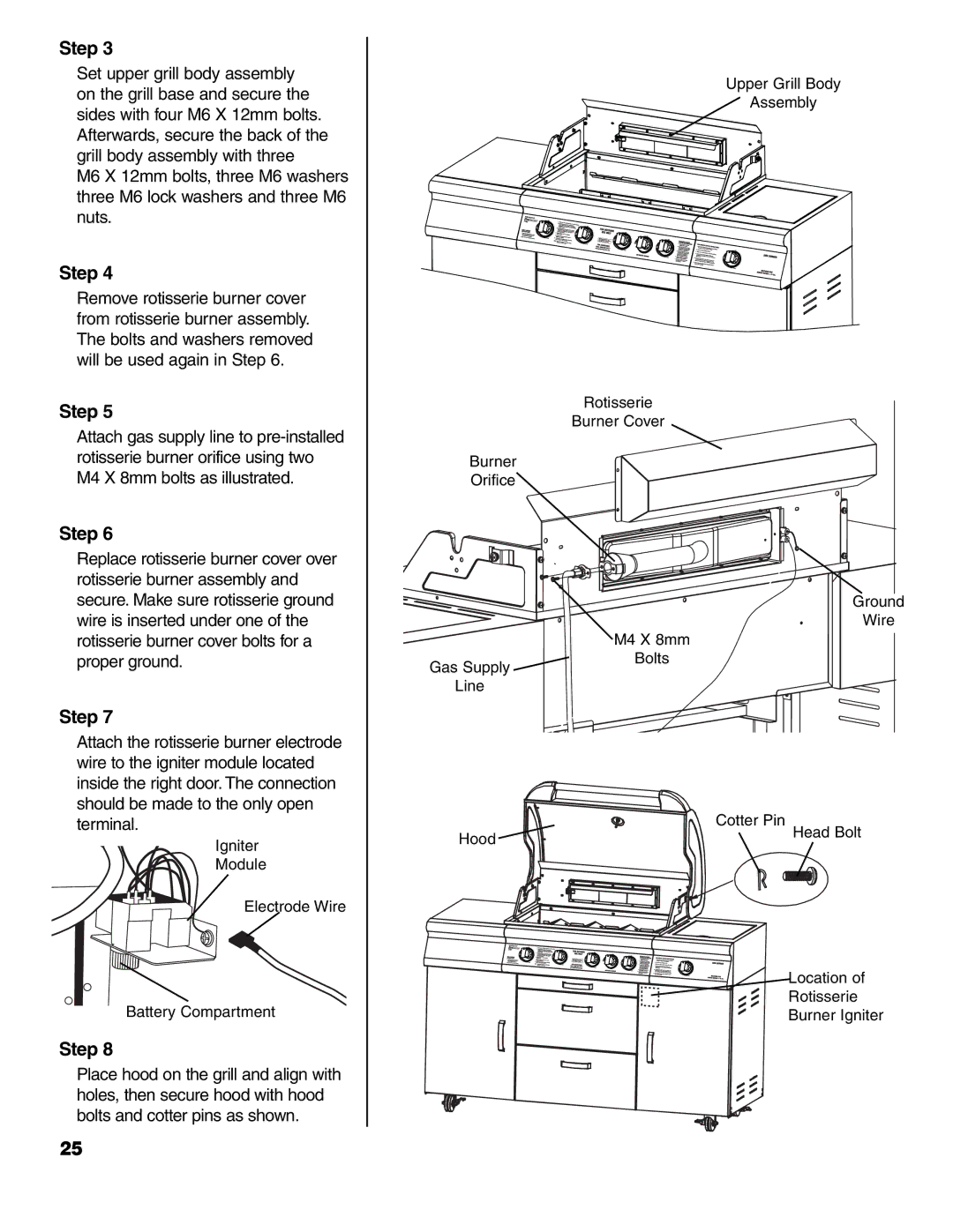
Step 5
Attach gas supply line to
Step 6
Replace rotisserie burner cover over rotisserie burner assembly and secure. Make sure rotisserie ground wire is inserted under one of the rotisserie burner cover bolts for a
Rotisserie
Burner Cover
Burner
Orifice
M4 X 8mm
Upper Grill Body
Assembly
Ground
Wire
proper ground.
Step 7
Gas Supply
Line
Bolts
Attach the rotisserie burner electrode wire to the igniter module located inside the right door. The connection should be made to the only open terminal.
Igniter
Module
Electrode Wire
Battery Compartment
Step 8
Place hood on the grill and align with holes, then secure hood with hood bolts and cotter pins as shown.
Hood ![]()
Cotter Pin
Head Bolt
Location of
Rotisserie
Burner Igniter
25