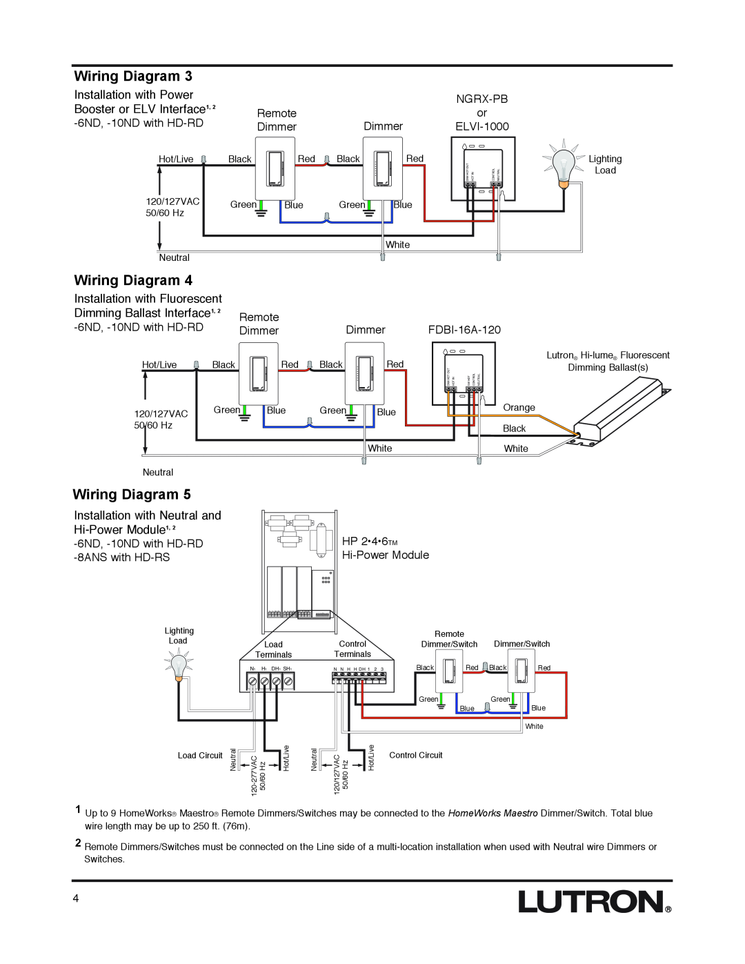
Wiring Diagram 3 |
|
|
Installation with Power |
|
|
Booster or ELV Interface1, 2 | Remote |
|
| ||
Dimmer | Dimmer |
or
Hot/Live Black
120/127VAC Green 50/60 Hz
Neutral
Wiring Diagram 4
Red ![]() Black
Black
Blue Green ![]()
Red
Blue
White
DIM HOT OUT | HOT IN | CONTROL | NEUTRAL |
![]()
![]()
![]() Lighting
Lighting ![]()
![]() Load
Load
Installation with Fluorescent |
|
|
|
| |
Dimming Ballast Interface1, 2 | Remote |
|
| ||
| Dimmer | ||||
| Dimmer | ||||
Hot/Live | Black |
| Red | Black | Red |
120/127VAC | Green | Blue | Green | Blue | |
50/60 Hz |
|
|
|
|
|
|
|
|
|
| White |
Neutral |
|
|
|
|
|
|
| Lutron® |
DIM HOT OUT HOT IN |
| Dimming Ballast(s) |
SW HOT | CONTROL NEUTRAL | |
|
| Orange |
|
| Black |
|
| White |
Wiring Diagram 5
Installation with Neutral and Hi-Power Module1, 2
Lighting
Load
|
|
| HP 2•4•6TM |
|
|
|
| ||
|
|
|
|
|
| ||||
| N H DH SH | N H DH SH | N H DH SH |
|
|
|
|
|
|
|
|
|
|
|
|
| Remote |
|
|
| Load |
| Control |
|
| Dimmer/Switch | Dimmer/Switch | ||
Terminals | Terminals |
|
|
|
|
|
| ||
N1 | H1 DH1 | SH1 | N N H H DH 1 | 2 | 3 | Black | Red | Black | Red |
|
|
|
|
|
| Green | Green |
| |
|
|
|
|
|
|
| Blue |
| Blue |
|
|
|
|
|
|
|
|
| White |
Load Circuit
Neutral |
|
|
|
|
|
|
|
| |||
|
|
| |||
| |||||
Hot/Live | Neutral |
|
|
|
|
|
| Hot/Live |
|
|
| 120/127VAC 50/60 Hz | |||||
|
|
| ||||||
| ||||||||
Control Circuit
1
2
Up to 9 HomeWorks® Maestro® Remote Dimmers/Switches may be connected to the HomeWorks Maestro Dimmer/Switch. Total blue wire length may be up to 250 ft. (76m).
Remote Dimmers/Switches must be connected on the Line side of a
4