|
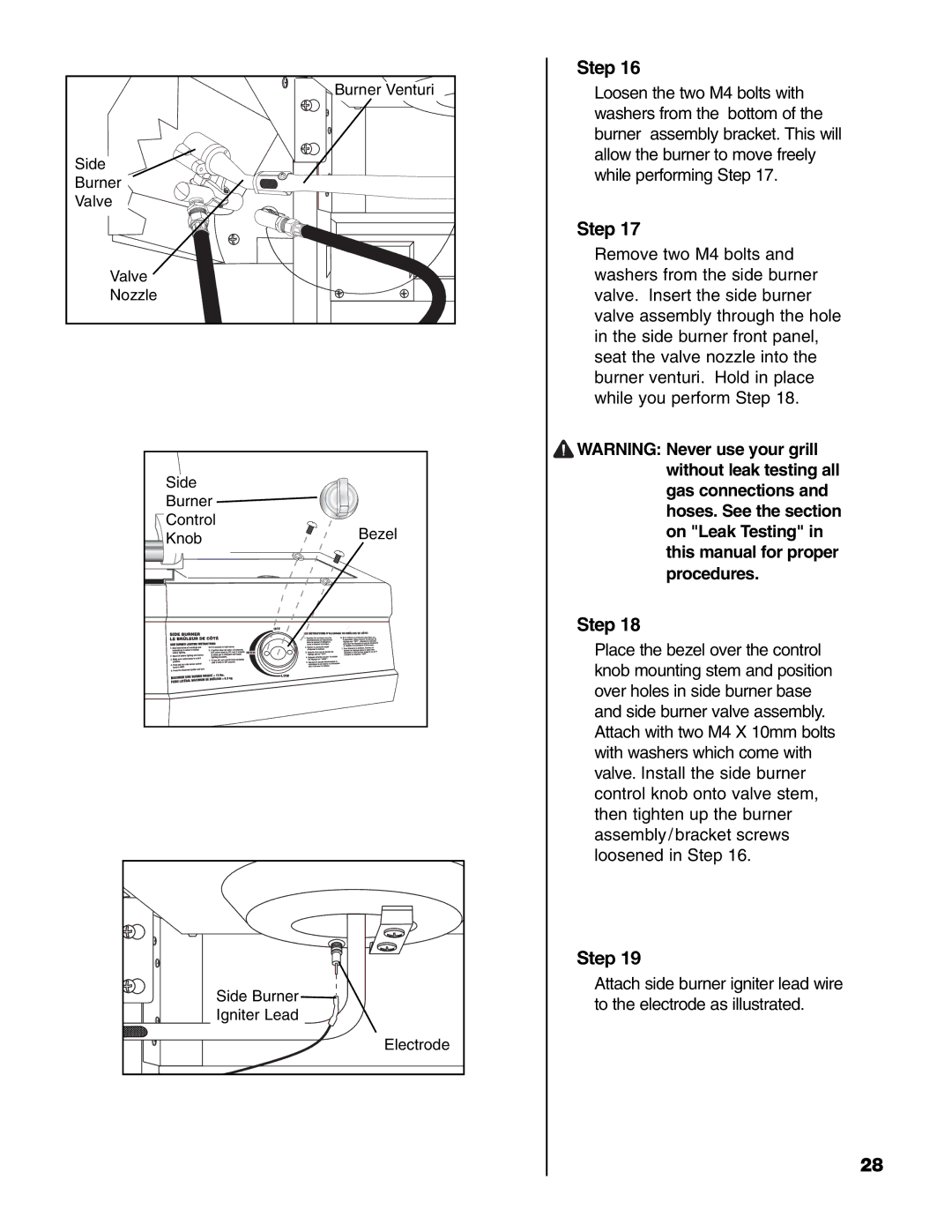
| Step 16 | |
| Burner Venturi | Loosen the two M4 bolts with | |
|
| washers from the bottom of the | |
|
| burner assembly bracket. This will | |
Side |
| allow the burner to move freely | |
| while performing Step 17. | ||
Burner |
| ||
|
| ||
Valve |
|
| |
|
| Step 17 | |
|
| Remove two M4 bolts and | |
Valve |
| washers from the side burner | |
Nozzle |
| valve. Insert the side burner | |
|
| valve assembly through the hole | |
|
| in the side burner front panel, | |
|
| seat the valve nozzle into the | |
|
| burner venturi. Hold in place | |
|
| while you perform Step 18. | |
|
| WARNING: Never use your grill | |
Side |
| without leak testing all | |
| gas connections and | ||
Burner |
| ||
| hoses. See the section | ||
Control |
| ||
Bezel | on "Leak Testing" in | ||
Knob | |||
|
| this manual for proper | |
|
| procedures. | |
|
| Step 18 | |
|
| Place the bezel over the control | |
|
| knob mounting stem and position | |
|
| over holes in side burner base | |
|
| and side burner valve assembly. | |
|
| Attach with two M4 X 10mm bolts | |
|
| with washers which come with | |
|
| valve. Install the side burner | |
|
| control knob onto valve stem, | |
|
| then tighten up the burner | |
|
| assembly/bracket screws | |
|
| loosened in Step 16. | |
|
| Step 19 | |
| Side Burner | Attach side burner igniter lead wire | |
| to the electrode as illustrated. | ||
| Igniter Lead | ||
|
| ||
| Electrode |
| |
|
| 28 |
