MODELS 350 • 350BK • 350BR • 355 • 355BK • 355BR 356 • 356BK • 356BR • 358
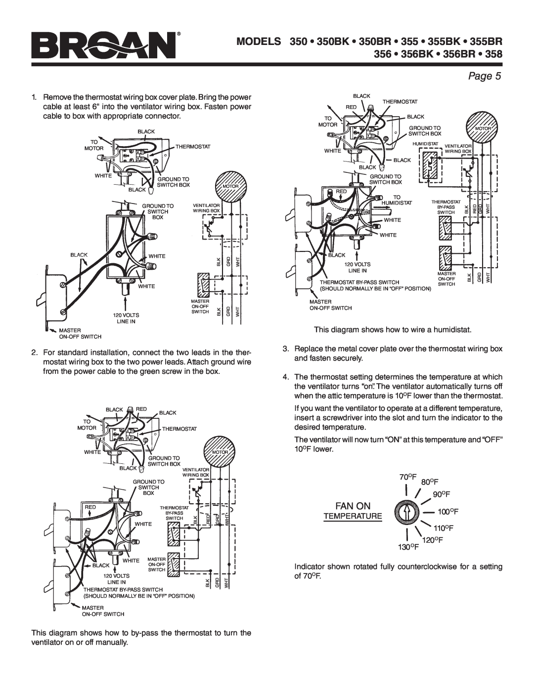
1.Remove the thermostat wiring box cover plate. Bring the power cable at least 6" into the ventilator wiring box. Fasten power cable to box with appropriate connector.
BLACK
TO
MOTORTHERMOSTAT
|
| WHITE | GROUND TO |
|
|
|
|
|
|
|
|
|
|
| |
|
|
| SWITCH BOX |
|
| MOTOR | |
|
|
| BLACK |
|
|
|
|
|
|
| GROUND TO | VENTILATOR |
|
| |
|
|
| SWITCH | WIRING BOX |
|
| |
|
|
| BOX |
|
|
|
|
B | LACK |
| WHITE |
| BLK | GRD | WHT |
|
|
| WHITE |
| |||
|
|
|
|
|
|
| |
|
|
|
| MASTER |
|
|
|
|
|
| 120 VOLTS | BLK | GRD | WHT | |
|
|
| SWITCH | ||||
|
|
|
|
|
|
| |
LINE IN
MASTER
2.For standard installation, connect the two leads in the ther- mostat wiring box to the two power leads. Attach ground wire from the power cable to the green screw in the box.
BLACK | RED | BLACK |
|
|
|
| |
|
|
|
|
|
|
| |
TO |
|
|
|
|
|
|
|
MOTOR |
|
| THERMOSTAT |
|
|
| |
WHITE |
|
|
|
|
| MOTOR | |
|
|
| GROUND TO |
|
|
|
|
BLACK |
| SWITCH BOX |
|
|
|
| |
| VENTILATOR |
|
| ||||
|
|
| WIRING BOX |
|
| ||
| GROUND TO |
|
|
|
| ||
| SWITCH |
|
|
|
| ||
|
| BOX |
|
|
|
| |
RED |
|
| THERMOSTAT |
|
|
|
|
|
|
| BLK | RED | GRD | WHT | |
|
|
| SWITCH | ||||
| WHITE |
|
|
|
| ||
WHITE |
| MASTER |
|
|
|
| |
BLACK |
|
|
|
|
|
| |
|
|
| SWITCH |
|
|
|
|
120 VOLTS |
|
|
|
| BLK | GRD | WHT |
LINE IN |
|
|
|
| |||
THERMOSTAT
(SHOULD NORMALLY BE IN “OFF” POSITION)
MASTER
Page 5
BLACK
|
|
|
|
|
|
|
|
| THERMOSTAT |
|
|
|
|
| |
|
| RED |
|
|
|
|
| ||||||||
TO |
|
|
|
|
|
| BLACK |
|
|
|
|
| |||
|
|
|
|
|
|
|
|
|
|
|
| ||||
MOTOR |
|
|
|
|
|
| GROUND TO |
|
| MOTOR | |||||
|
|
|
|
|
|
|
|
|
|
| |||||
|
|
|
|
|
|
|
|
| SWITCH BOX |
|
|
|
| ||
|
|
|
|
|
|
|
|
| HUMIDISTAT | VENTILATOR |
|
| |||
WHITE |
|
|
|
|
|
|
|
|
|
| |||||
|
|
|
|
|
|
|
| WIRING BOX |
|
| |||||
|
|
|
|
|
|
|
|
| BLACK |
|
|
|
|
| |
|
|
|
|
| BLACK |
|
|
|
|
| |||||
|
|
|
|
|
|
|
| GROUND TO |
|
|
|
|
| ||
|
|
|
|
|
|
|
| SWITCH BOX |
|
|
|
|
| ||
| RED |
|
|
|
|
|
| TO |
|
|
|
|
| ||
|
|
|
|
|
|
|
|
| THERMOSTAT |
|
|
| |||
|
|
|
|
|
|
|
|
| HUMIDISTAT | BLK | RED GRD | WHT | |||
|
|
|
|
|
|
|
|
|
| SWITCH | |||||
|
|
|
|
|
|
|
|
|
|
|
|
| |||
|
|
|
|
|
|
|
|
| WHITE |
|
|
|
|
| |
|
|
|
|
|
|
|
|
|
|
|
|
|
| ||
|
|
|
|
|
|
|
|
|
|
|
|
|
| ||
| BLACK |
|
|
|
|
|
| WHITE |
|
|
|
|
| ||
|
|
|
|
|
|
|
|
|
|
|
| ||||
|
|
|
|
|
|
|
|
|
|
|
| ||||
|
|
|
|
|
|
|
|
|
|
|
| ||||
|
|
|
|
|
|
|
|
|
|
|
|
| |||
|
|
|
|
|
|
|
|
|
|
|
|
| |||
|
| 120 VOLTS |
|
|
|
|
| ||||||||
|
|
|
|
|
|
| |||||||||
|
|
| LINE IN | MASTER | BLK | GRD | WHT | ||||||||
|
|
|
|
|
|
|
|
|
| ||||||
THERMOSTAT | |||||||||||||||
|
|
| |||||||||||||
SWITCH |
|
|
| ||||||||||||
(SHOULD NORMALLY BE IN “OFF” POSITION) |
|
|
|
|
| ||||||||||
MASTER
This diagram shows how to wire a humidistat.
3.Replace the metal cover plate over the thermostat wiring box and fasten securely.
4.The thermostat setting determines the temperature at which the ventilator turns “on”. The ventilator automatically turns off when the attic temperature is 10OF lower than the thermostat.
If you want the ventilator to operate at a different temperature, insert a screwdriver into the slot and turn the indicator to the desired temperature.
The ventilator will now turn “ON” at this temperature and “OFF” 10OF lower.
70OF 80OF
90OF
FAN ON
TEMPERATURE100OF 110OF
130OF 120OF
Indicator shown rotated fully counterclockwise for a setting of 70OF.
This diagram shows how to