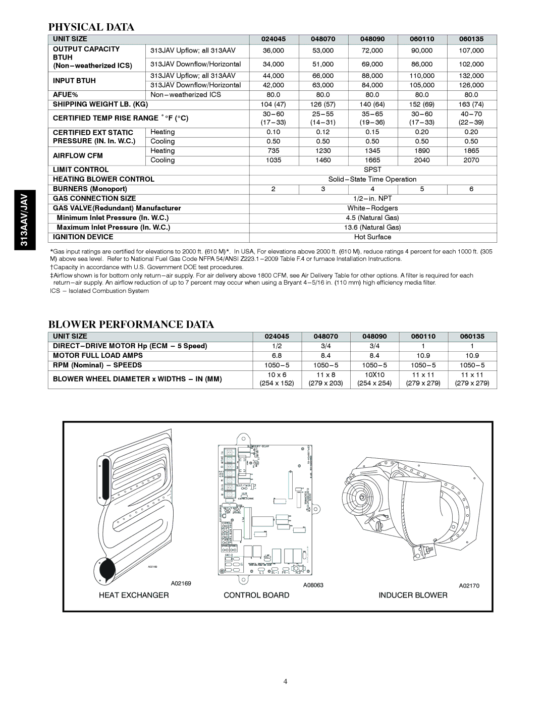
313AAV specifications
The Bryant 313AAV is a state-of-the-art air conditioning unit renowned for its reliable performance and energy-efficient design. Crafted for residential use, this model provides optimal cooling while ensuring low operational costs. Its standout feature is the variable-speed compressor, which adjusts its output based on the cooling needs of your home. This not only leads to more consistent temperatures but also enhances energy efficiency, allowing homeowners to save on their utility bills.One of the key technologies employed in the Bryant 313AAV is the Infinity Control system. This smart thermostat allows users to manage their home's temperature remotely via a smartphone app. The system is compatible with Wi-Fi, enabling seamless connectivity and ease of use. Additionally, the unit's advanced communication technology enables it to monitor system performance and send alerts for maintenance, ensuring that the air conditioning system operates at its best.
The Bryant 313AAV is designed with sound reduction technology, which minimizes operational noise, making it an excellent choice for residential environments where peace and quiet are a priority. Its cabinet is constructed for durability and features enhanced insulation to further reduce noise levels.
Another impressive characteristic of the Bryant 313AAV is its SEER rating. With Seasonal Energy Efficiency Ratio (SEER) ratings of up to 20, this model exceeds the minimum efficiency standards set by the U.S. government, making it an environmentally friendly option. This high SEER rating means that the unit consumes less energy while providing superior cooling performance.
Installation is made straightforward thanks to the unit's compact size and flexible design. Additionally, the Bryant 313AAV is equipped with EcoWise refrigerant, which is designed to be more environmentally responsible while ensuring efficient cooling performance.
In summary, the Bryant 313AAV air conditioning unit stands out due to its energy efficiency, advanced technology features, and quiet operation. It is an ideal choice for homeowners looking to enhance their comfort while keeping energy costs in check. With its reliable performance and innovative characteristics, the Bryant 313AAV is well-equipped to meet the cooling demands of today's households.

