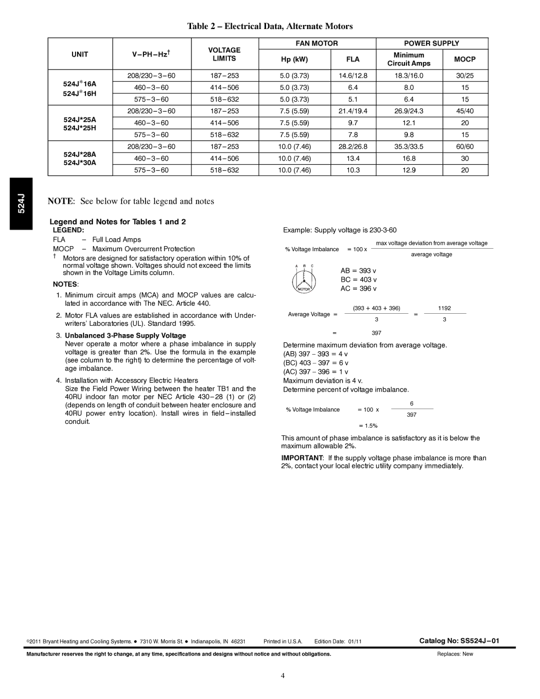
542J specifications
Bryant 542J is a high-efficiency gas furnace that stands out for its reliability and advanced heating technologies. Designed to deliver consistent warmth and comfort in residential settings, it combines innovative engineering with energy-efficient features.One of the key characteristics of the Bryant 542J is its two-stage heating capability. This means that the furnace can adjust its heat output according to the heating demands of your home. During milder weather, it operates at a lower stage, consuming less energy while still maintaining a comfortable environment. When the temperatures drop, the furnace shifts to its higher capacity, providing the necessary warmth efficiently. This not only enhances comfort but also contributes to lower energy bills.
In addition to its two-stage operation, the Bryant 542J also incorporates a variable-speed blower motor. This technology allows the furnace to adjust the airflow depending on the heating requirements, ensuring an even distribution of warm air throughout the home. The variable-speed blower also operates more quietly than conventional fixed-speed motors, creating a serene indoor environment.
Energy efficiency is a hallmark of the Bryant 542J, boasting an Annual Fuel Utilization Efficiency (AFUE) rating of up to 96.5%. This impressive rating means that a significant portion of the energy consumed is effectively converted into usable heat, resulting in substantial savings on heating costs over time. Furthermore, the furnace is equipped with a sealed combustion system that draws air from outside the home, minimizing energy waste and improving indoor air quality.
Diagnostic features are another highlight of the Bryant 542J, which come equipped with SmartEvap technology. This allows the unit to self-diagnose potential issues, providing homeowners with peace of mind and simplifying maintenance procedures.
Durability is also a key feature of the Bryant 542J. It is constructed with high-quality materials designed to withstand harsh winter conditions, ensuring a long lifespan and reliable performance. Its compact design also allows for flexible installation, making it suitable for various residential layouts.
In summary, the Bryant 542J is more than just a gas furnace; it is a sophisticated heating solution that combines efficiency, comfort, and reliability. With features such as two-stage heating, a variable-speed blower, high AFUE ratings, and advanced diagnostics, it is an excellent choice for homeowners seeking an efficient and effective heating system.

