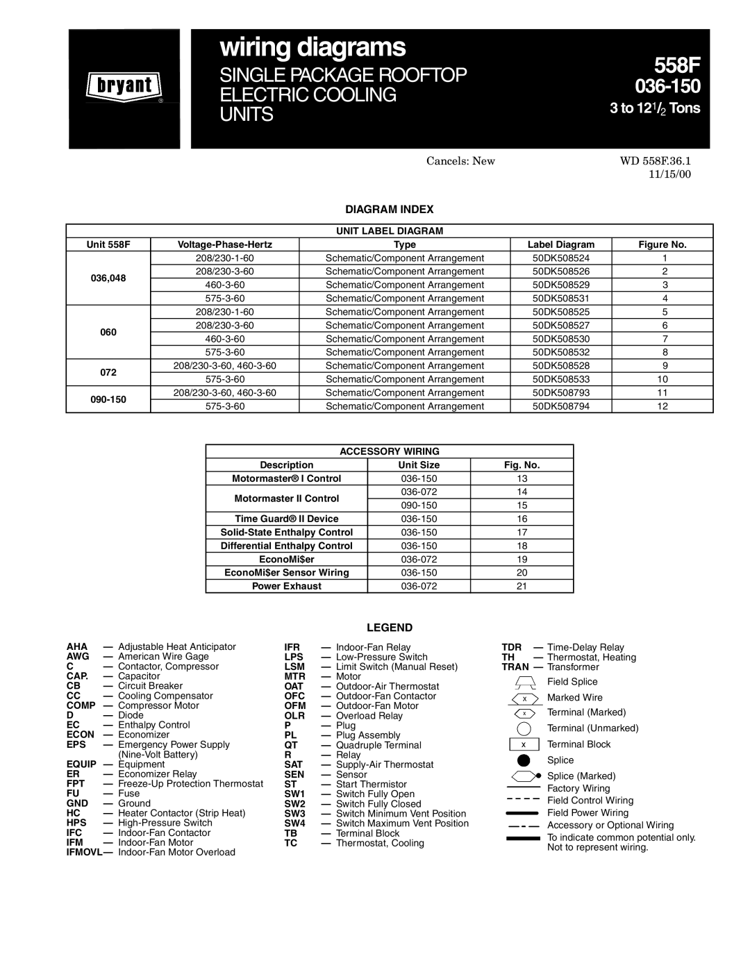
558F.36.1 specifications
The Bryant 558F.36.1 is a cutting-edge heating, ventilation, and air conditioning (HVAC) solution that efficiently combines advanced technologies with innovative design. This model is part of Bryant's robust lineup, providing users with reliable comfort and excellent energy performance.One of the standout features of the Bryant 558F.36.1 is its environmentally friendly refrigerant, R-410A. This refrigerant is designed to minimize environmental impact while maximizing system performance. The HVAC unit is also equipped with variable-speed technology, which allows for precise temperature control and enhanced energy efficiency. By adjusting the motor speed, the system can operate at different capacities, ensuring optimal comfort and reduced energy consumption.
The Bryant 558F.36.1 also boasts a high Seasonal Energy Efficiency Ratio (SEER) rating. This rating measures the cooling efficiency of air conditioning systems over an entire cooling season. With a high SEER rating, users can expect lower energy bills and environmental benefits, as the system requires less energy to maintain comfortable indoor temperatures.
In terms of design, the unit features a compact and sleek appearance, making it suitable for installation in a variety of home settings. The cabinet is constructed with durable materials, ensuring longevity and resistance to outdoor elements. Additionally, the quieter operation of the Bryant 558F.36.1 enhances indoor comfort, making it an ideal choice for homes where noise is a concern.
Another characteristic of the Bryant 558F.36.1 is its compatibility with smart home technology. It can be integrated with smart thermostats, allowing users to control their HVAC system remotely through mobile applications. This feature not only adds convenience but also enables users to monitor and optimize energy usage.
Furthermore, the Bryant 558F.36.1 comes equipped with a user-friendly control panel that provides easy access to various settings and configurations. This intuitive interface allows homeowners to customize their comfort preferences without hassle.
In conclusion, the Bryant 558F.36.1 is a state-of-the-art HVAC solution that excels in energy efficiency, environmental responsibility, and user convenience. With its innovative features and reliable performance, it is an excellent investment for any homeowner seeking to enhance their indoor comfort while minimizing energy costs.

