DIMENSIONS | ELECTRICAL CONNECTIONS |
UNIT | A |
| B |
| C |
| D |
|
| E |
| F |
|
|
|
|
|
|
|
|
| ||||
| With Aluminum Coils (Standard) |
|
|
| ||||||||
|
|
|
|
|
|
|
|
|
|
|
|
|
569C072 | 2 | 4 | — |
| 4 |
| 16 | |||||
|
|
|
|
|
|
|
| 16 | ||||
569C090 |
| 2 | 16 |
|
|
| ||||||
|
|
|
|
|
|
|
| 16 | 16 | |||
569C120 |
|
|
|
|
|
| ||||||
|
|
|
|
|
|
|
|
|
| 16 | 16 | |
576B090 |
| 4 | 16 |
|
|
| ||||||
|
|
|
|
|
|
|
| 16 | 16 | |||
576B102 |
|
| 16 |
|
|
| ||||||
|
|
|
|
|
|
|
|
| 16 | 16 | ||
576B120 |
|
| 16 |
|
|
| ||||||
|
|
|
|
|
|
|
|
| 16 | 16 | ||
|
| With Copper Coils (Optional) |
|
|
| |||||||
|
|
|
|
|
|
|
|
|
|
|
|
|
569C072 |
|
| — |
| 4 |
| 16 | |||||
|
|
|
|
|
|
|
|
|
| 16 | ||
569C090 | 2 |
| 16 |
|
|
| ||||||
|
|
|
|
|
|
|
| 16 | 16 | |||
569C120 |
|
|
|
|
| |||||||
|
|
|
|
|
|
|
|
|
| 16 | 16 | |
576B090 | 2 | 2 | 16 |
|
|
| ||||||
|
|
|
|
|
|
| 16 | 16 | ||||
576B102 | 2 |
| 16 |
|
|
| ||||||
|
|
|
|
|
|
|
| 16 | 16 | |||
576B120 | 2 |
| 16 |
|
|
| ||||||
|
|
|
|
|
|
|
| 16 | 16 | |||
CONNECTION SIZES
AA |
|
| 13/ ″ | Dia Field Power Supply Hole | |||||||||
|
|
|
| 8 |
|
|
|
|
|
|
|
| |
BB |
|
| 2″ Dia Power Supply Knockout | ||||||||||
|
|
|
|
|
|
|
|
|
|
|
| ||
CC |
|
| 21/ ″ | Dia Power Supply Knockout | |||||||||
|
|
|
| 2 |
|
|
|
|
|
|
|
| |
DD |
|
| 7/ ″ Dia Field Control Wiring Hole | ||||||||||
|
|
|
| 8 |
|
|
|
|
|
|
|
|
|
| SERVICE VALVE CONNECTIONS |
|
| ||||||||||
|
|
|
|
|
|
|
|
|
|
| |||
UNIT |
|
| SUCTION |
|
| LIQUID | |||||||
|
|
|
|
|
|
|
|
|
|
|
|
| |
569C072 |
| 11/ | ″ |
|
| 1/ | ″ | ||||||
|
|
|
|
|
| 8 |
|
|
| 2 |
|
| |
569C090 |
| 11/ | ″ |
|
| 1/ | ″ | ||||||
|
|
|
|
|
| 8 |
|
|
| 2 |
|
| |
569C120 |
| 11/ | ″ |
|
| 5/ | ″ | ||||||
|
|
|
|
|
| 8 |
|
|
| 8 |
|
| |
576B090 |
| 11/ | ″ |
|
| 1/ | ″ | ||||||
|
|
|
|
|
| 8 |
|
|
| 2 |
|
| |
576B102 |
| 11/ | ″ |
|
| 5/ | ″ | ||||||
|
|
|
|
|
| 8 |
|
|
| 8 |
|
| |
576B120 |
| 11/ | ″ |
|
| 5/ | ″ | ||||||
|
|
|
|
|
| 8 |
|
|
| 8 |
|
| |
|
|
| WEIGHT CHART (lb) |
|
|
|
| ||||||
|
|
|
|
|
|
|
|
|
|
| |||
UNIT |
| STD UNIT |
| CORNER W | CORNER X | ||||||||
| Al | Cu |
| Al | Cu | Al |
| Cu | |||||
|
|
|
| ||||||||||
569C072 |
| 340 | 386 |
|
| 86 | 106 | 53 |
| 65 | |||
569C090 |
| 392 | 460 |
|
| 91 | 120 | 84 |
| 100 | |||
569C120 |
| 426 | 503 |
|
| 96 | 126 | 99 |
| 126 | |||
576B090 |
| 510 | 578 |
| 114 | 143 | 89 |
| 106 | ||||
576B102 |
| 564 | 632 |
| 133 | 161 | 97 |
| 114 | ||||
576B120 |
| 564 | 632 |
| 133 | 161 | 97 |
| 114 | ||||
|
|
|
|
|
|
|
|
| |||||
UNIT |
| CORNER Y |
|
|
| CORNER Z | |||||||
| Al |
|
| Cu |
|
| Al |
|
|
| Cu | ||
|
|
|
|
|
|
|
|
| |||||
569C072 |
| 77 |
| 82 | 124 |
|
| 133 | |||||
569C090 |
| 105 |
| 113 | 113 |
|
| 127 | |||||
569C120 |
| 117 |
| 127 | 113 |
|
| 127 | |||||
576B090 |
| 133 |
| 142 | 173 |
|
| 187 | |||||
576B102 |
| 141 |
| 150 | 193 |
|
| 207 | |||||
576B120 |
| 141 |
| 150 | 193 |
|
| 207 | |||||
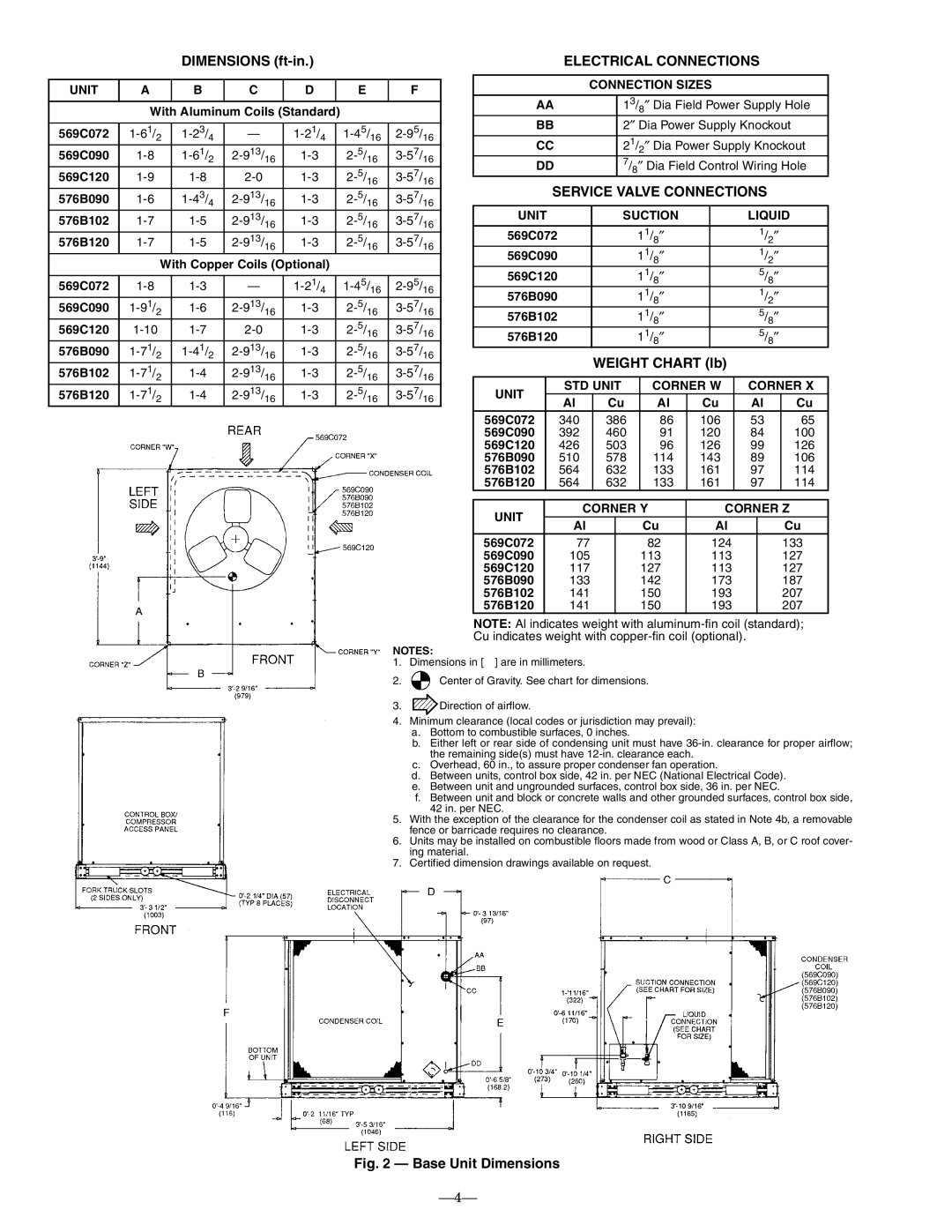
NOTE: Al indicates weight with
NOTES:
1. Dimensions in [ ] are in millimeters.
2.![]() Center of Gravity. See chart for dimensions.
Center of Gravity. See chart for dimensions.
3.![]() Direction of airflow.
Direction of airflow.
4.Minimum clearance (local codes or jurisdiction may prevail):
a.Bottom to combustible surfaces, 0 inches.
b.Either left or rear side of condensing unit must have
c.Overhead, 60 in., to assure proper condenser fan operation.
d.Between units, control box side, 42 in. per NEC (National Electrical Code).
e.Between unit and ungrounded surfaces, control box side, 36 in. per NEC.
f.Between unit and block or concrete walls and other grounded surfaces, control box side, 42 in. per NEC.
5.With the exception of the clearance for the condenser coil as stated in Note 4b, a removable fence or barricade requires no clearance.
6.Units may be installed on combustible floors made from wood or Class A, B, or C roof cover- ing material.
7.Certified dimension drawings available on request.