NOTE: Avoid contact between tubing and structure

OUTDOOR WALL INDOOR WALL

CAULK

LIQUID TUBE

VAPOR TUBE

INSULATION

THROUGH THE WALL

JOIST

HANGER STRAP

(AROUND VAPOR

TUBE ONLY)INSULATION VAPOR TUBE

1MIN.

LIQUID TUBE

SUSPENSION

A94208

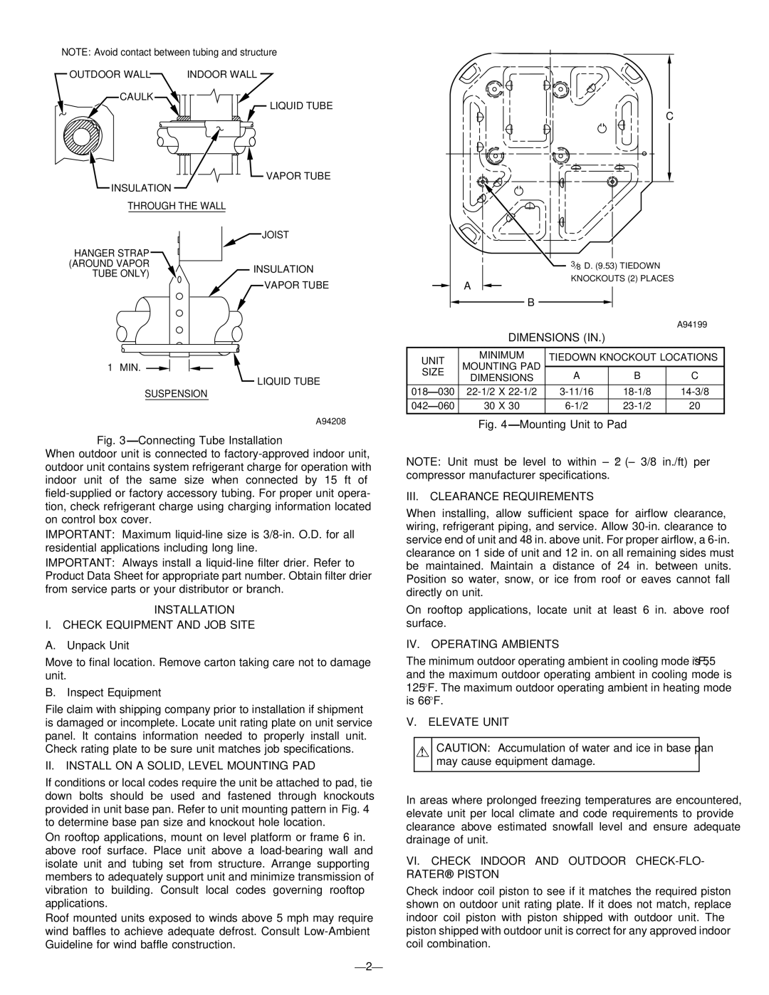
Fig. 3—Connecting Tube Installation

When outdoor unit is connected to factory-approved indoor unit, outdoor unit contains system refrigerant charge for operation with indoor unit of the same size when connected by 15 ft of field-supplied or factory accessory tubing. For proper unit opera- tion, check refrigerant charge using charging information located on control box cover.

IMPORTANT: Maximum liquid-line size is 3/8-in. O.D. for all residential applications including long line.

IMPORTANT: Always install a liquid-line filter drier. Refer to Product Data Sheet for appropriate part number. Obtain filter drier from service parts or your distributor or branch.

INSTALLATION

I. CHECK EQUIPMENT AND JOB SITE

A. Unpack Unit

Move to final location. Remove carton taking care not to damage unit.

B. Inspect Equipment

File claim with shipping company prior to installation if shipment is damaged or incomplete. Locate unit rating plate on unit service panel. It contains information needed to properly install unit. Check rating plate to be sure unit matches job specifications.

II. INSTALL ON A SOLID, LEVEL MOUNTING PAD

If conditions or local codes require the unit be attached to pad, tie down bolts should be used and fastened through knockouts provided in unit base pan. Refer to unit mounting pattern in Fig. 4 to determine base pan size and knockout hole location.

On rooftop applications, mount on level platform or frame 6 in. above roof surface. Place unit above a load-bearing wall and isolate unit and tubing set from structure. Arrange supporting members to adequately support unit and minimize transmission of vibration to building. Consult local codes governing rooftop applications.

Roof mounted units exposed to winds above 5 mph may require wind baffles to achieve adequate defrost. Consult Low-Ambient Guideline for wind baffle construction.

—2—

C


38D. (9.53) TIEDOWN


A


KNOCKOUTS (2) PLACES


B


A94199


DIMENSIONS (IN.)


UNIT

MINIMUM

TIEDOWN KNOCKOUT LOCATIONS

MOUNTING PAD


SIZE


A

B


C

DIMENSIONS


018—030

22-1/2 X 22-1/2

3-11/16


18-1/8


14-3/8

042—060

30 X 30

6-1/2


23-1/2


20

Fig. 4—Mounting Unit to Pad

NOTE: Unit must be level to within ± 2 ° (± 3/8 in./ft) per compressor manufacturer specifications.

III. CLEARANCE REQUIREMENTS

When installing, allow sufficient space for airflow clearance, wiring, refrigerant piping, and service. Allow 30-in. clearance to service end of unit and 48 in. above unit. For proper airflow, a 6-in. clearance on 1 side of unit and 12 in. on all remaining sides must be maintained. Maintain a distance of 24 in. between units. Position so water, snow, or ice from roof or eaves cannot fall directly on unit.

On rooftop applications, locate unit at least 6 in. above roof surface.

IV. OPERATING AMBIENTS

The minimum outdoor operating ambient in cooling mode is 55°F, and the maximum outdoor operating ambient in cooling mode is 125°F. The maximum outdoor operating ambient in heating mode is 66°F.

V. ELEVATE UNIT

CAUTION: Accumulation of water and ice in base pan may cause equipment damage.

In areas where prolonged freezing temperatures are encountered, elevate unit per local climate and code requirements to provide clearance above estimated snowfall level and ensure adequate drainage of unit.

VI. CHECK INDOOR AND OUTDOOR CHECK-FLO- RATER® PISTON

Check indoor coil piston to see if it matches the required piston shown on outdoor unit rating plate. If it does not match, replace indoor coil piston with piston shipped with outdoor unit. The piston shipped with outdoor unit is correct for any approved indoor coil combination.

Page 2
Image 2
Bryant 661C, 661G, 661S Installation Check Equipment and JOB Site, II. Install on a SOLID, Level Mounting PAD, Dimensions

661S, 661C, 661G specifications

The Bryant 661 series, comprising the models 661G, 661C, and 661S, represents a significant advance in heating and cooling technology, offering efficiency, reliability, and smart capabilities for modern homes. These models are designed to cater to various climate conditions while ensuring optimal comfort and energy savings.

The Bryant 661G model is primarily a gas furnace that boasts impressive AFUE (Annual Fuel Utilization Efficiency) ratings, which can exceed 96%. This efficiency translates into substantial savings on energy bills, making it an environmentally friendly choice. The 661G features a variable-speed blower motor, which adjusts airflow to meet specific heating needs. Additionally, its dual-stage gas valve allows for enhanced comfort and efficiency, providing a quiet operation and steady temperature control throughout the home.

The Bryant 661C model stands out with its focus on air conditioning capabilities. It utilizes advanced inverter technology that allows for precise temperature control and enhanced energy efficiency. With high SEER (Seasonal Energy Efficiency Ratio) ratings, the 661C significantly reduces energy consumption during hot months. Furthermore, the model is equipped with advanced filtration systems that ensure high indoor air quality by capturing allergens and pollutants, making it an excellent choice for allergy sufferers.

Lastly, the Bryant 661S is a comprehensive solution combining both heating and cooling in a single unit. This model is designed for versatility and efficiency, making it suitable for various residential applications. It offers smart technology integration, allowing homeowners to control their HVAC systems remotely via smartphone apps. The 661S's high-efficiency heat pump technology provides substantial savings in energy costs while maintaining optimal comfort year-round.

All three models feature durable construction with corrosion-resistant materials, ensuring longevity and minimal maintenance. The Bryant Comfort Shield technology enhances operational reliability by providing protection against environmental stressors. Moreover, the ease of installation and compatibility with existing Bryant systems adds to their appeal.

In conclusion, the Bryant 661G, 661C, and 661S models combine modern technology with energy-efficient performance, making them ideal choices for those looking to improve their home comfort while reducing energy costs. With their advanced features, homeowners can enjoy a cozy living environment while contributing to a more sustainable future.