PISTON BODY

PISTON

PISTON

RETAINER

STRAINER

SWEAT/FLARE ADAPTER

A97512

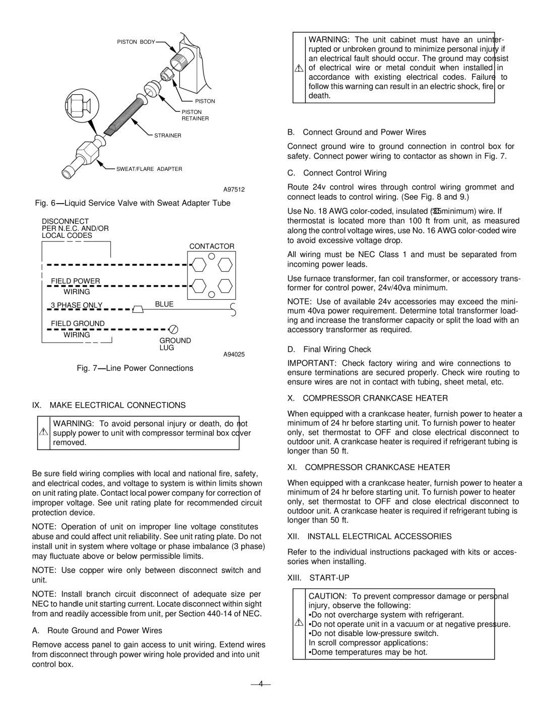
Fig. 6—Liquid Service Valve with Sweat Adapter Tube

DISCONNECT

PER N.E.C. AND/OR

LOCAL CODES

CONTACTOR

FIELD POWER

WIRING

3 PHASE ONLY

BLUE

FIELD GROUND

WIRING

GROUND

LUG

A94025

Fig. 7—Line Power Connections

IX. MAKE ELECTRICAL CONNECTIONS

WARNING: To avoid personal injury or death, do not supply power to unit with compressor terminal box cover removed.

Be sure field wiring complies with local and national fire, safety, and electrical codes, and voltage to system is within limits shown on unit rating plate. Contact local power company for correction of improper voltage. See unit rating plate for recommended circuit protection device.

NOTE: Operation of unit on improper line voltage constitutes abuse and could affect unit reliability. See unit rating plate. Do not install unit in system where voltage or phase imbalance (3 phase) may fluctuate above or below permissible limits.

NOTE: Use copper wire only between disconnect switch and unit.

NOTE: Install branch circuit disconnect of adequate size per NEC to handle unit starting current. Locate disconnect within sight from and readily accessible from unit, per Section 440-14 of NEC.

A. Route Ground and Power Wires

Remove access panel to gain access to unit wiring. Extend wires from disconnect through power wiring hole provided and into unit control box.

WARNING: The unit cabinet must have an uninter- rupted or unbroken ground to minimize personal injury if an electrical fault should occur. The ground may consist of electrical wire or metal conduit when installed in accordance with existing electrical codes. Failure to follow this warning can result in an electric shock, fire, or death.

B. Connect Ground and Power Wires

Connect ground wire to ground connection in control box for safety. Connect power wiring to contactor as shown in Fig. 7.

C. Connect Control Wiring

Route 24v control wires through control wiring grommet and connect leads to control wiring. (See Fig. 8 and 9.)

Use No. 18 AWG color-coded, insulated (35°C minimum) wire. If thermostat is located more than 100 ft from unit, as measured along the control voltage wires, use No. 16 AWG color-coded wire to avoid excessive voltage drop.

All wiring must be NEC Class 1 and must be separated from incoming power leads.

Use furnace transformer, fan coil transformer, or accessory trans- former for control power, 24v/40va minimum.

NOTE: Use of available 24v accessories may exceed the mini- mum 40va power requirement. Determine total transformer load- ing and increase the transformer capacity or split the load with an accessory transformer as required.

D. Final Wiring Check

IMPORTANT: Check factory wiring and wire connections to ensure terminations are secured properly. Check wire routing to ensure wires are not in contact with tubing, sheet metal, etc.

X. COMPRESSOR CRANKCASE HEATER

When equipped with a crankcase heater, furnish power to heater a minimum of 24 hr before starting unit. To furnish power to heater only, set thermostat to OFF and close electrical disconnect to outdoor unit. A crankcase heater is required if refrigerant tubing is longer than 50 ft.

XI. COMPRESSOR CRANKCASE HEATER

When equipped with a crankcase heater, furnish power to heater a minimum of 24 hr before starting unit. To furnish power to heater only, set thermostat to OFF and close electrical disconnect to outdoor unit. A crankcase heater is required if refrigerant tubing is longer than 50 ft.

XII. INSTALL ELECTRICAL ACCESSORIES

Refer to the individual instructions packaged with kits or acces- sories when installing.

XIII. START-UP

CAUTION: To prevent compressor damage or personal injury, observe the following:

•Do not overcharge system with refrigerant.

•Do not operate unit in a vacuum or at negative pressure. •Do not disable low-pressure switch.

In scroll compressor applications: •Dome temperatures may be hot.

—4—

Page 4
Image 4
Bryant 661S IX. Make Electrical Connections, XI. Compressor Crankcase Heater, XII. Install Electrical Accessories

661S, 661C, 661G specifications

The Bryant 661 series, comprising the models 661G, 661C, and 661S, represents a significant advance in heating and cooling technology, offering efficiency, reliability, and smart capabilities for modern homes. These models are designed to cater to various climate conditions while ensuring optimal comfort and energy savings.

The Bryant 661G model is primarily a gas furnace that boasts impressive AFUE (Annual Fuel Utilization Efficiency) ratings, which can exceed 96%. This efficiency translates into substantial savings on energy bills, making it an environmentally friendly choice. The 661G features a variable-speed blower motor, which adjusts airflow to meet specific heating needs. Additionally, its dual-stage gas valve allows for enhanced comfort and efficiency, providing a quiet operation and steady temperature control throughout the home.

The Bryant 661C model stands out with its focus on air conditioning capabilities. It utilizes advanced inverter technology that allows for precise temperature control and enhanced energy efficiency. With high SEER (Seasonal Energy Efficiency Ratio) ratings, the 661C significantly reduces energy consumption during hot months. Furthermore, the model is equipped with advanced filtration systems that ensure high indoor air quality by capturing allergens and pollutants, making it an excellent choice for allergy sufferers.

Lastly, the Bryant 661S is a comprehensive solution combining both heating and cooling in a single unit. This model is designed for versatility and efficiency, making it suitable for various residential applications. It offers smart technology integration, allowing homeowners to control their HVAC systems remotely via smartphone apps. The 661S's high-efficiency heat pump technology provides substantial savings in energy costs while maintaining optimal comfort year-round.

All three models feature durable construction with corrosion-resistant materials, ensuring longevity and minimal maintenance. The Bryant Comfort Shield technology enhances operational reliability by providing protection against environmental stressors. Moreover, the ease of installation and compatibility with existing Bryant systems adds to their appeal.

In conclusion, the Bryant 661G, 661C, and 661S models combine modern technology with energy-efficient performance, making them ideal choices for those looking to improve their home comfort while reducing energy costs. With their advanced features, homeowners can enjoy a cozy living environment while contributing to a more sustainable future.