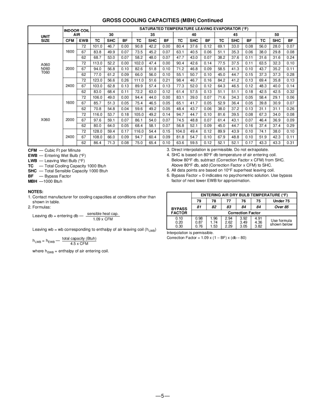
GROSS COOLING CAPACITIES (MBH) Continued


INDOOR COIL


SATURATED TEMPERATURE LEAVING EVAPORATOR (°F)


UNIT

AIR


30


35


40


45


50


SIZE

CFM

EWB

TC

SHC

BF

TC

SHC

BF

TC

SHC

BF

TC

SHC

BF

TC

SHC

BF


72

101.0

46.7

0.00

90.8

42.2

0.00

80.4

37.6

0.12

69.1

33.0

0.08

56.0

28.0

0.07


1600


67

83.8

49.9

0.07

73.5

45.2

0.07

63.1

40.5

0.06

51.1

35.3

0.06

38.0

29.8

0.08


62

68.7

53.0

0.07

58.2

48.0

0.07

47.7

43.0

0.07

38.2

37.6

0.11

31.6

31.6

0.24


A060


72

113.0

52.2

0.00

102.0

47.4

0.00

90.4

42.6

0.14

77.5

37.5

0.11

63.5

32.3

0.10


N060

2000

67

94.0

56.8

0.10

82.6

51.8

0.10

71.2

46.8

0.09

58.5

41.3

0.10

43.7

35.2

0.11

T060


62

77.0

61.2

0.09

66.0

56.0

0.10

55.1

50.7

0.10

45.0

44.7

0.15

37.3

37.3

0.28


72

123.0

56.6

0.26

111.0

51.6

0.21

98.4

46.7

0.16

84.2

41.2

0.13

69.4

35.8

0.13


2400


67

103.0

62.8

0.13

89.9

57.4

0.13

77.3

52.0

0.12

64.3

46.5

0.12

48.3

40.0

0.14


62

83.0

68.4

0.11

72.2

63.0

0.12

61.4

57.5

0.13

51.1

51.1

0.18

42.5

42.5

0.32


72

106.0

49.0

0.00

94.4

44.0

0.00

83.1

39.0

0.07

71.6

34.3

0.05

58.4

29.1

0.06


1600


67

85.7

51.3

0.05

75.4

46.5

0.05

65.1

41.7

0.05

52.9

36.4

0.05

39.8

30.9

0.07


62

70.8

54.8

0.04

59.6

49.2

0.05

48.4

43.7

0.06

38.0

37.2

0.13

31.1

31.1

0.26


72

116.0

53.7

0.18

105.0

49.2

0.14

94.7

44.7

0.10

81.6

39.5

0.08

67.3

34.0

0.08

X060

2000


67

97.6

59.1

0.07

86.1

54.0

0.07

74.5

48.8

0.07

61.4

43.1

0.07

46.4

36.9

0.09


62

80.0

64.0

0.05

68.4

58.1

0.07

56.8

52.1

0.09

45.0

44.7

0.16

37.4

37.4

0.29


72

128.0

59.4

0.17

116.0

54.4

0.15

104.0

49.4

0.12

89.9

43.9

0.10

74.1

38.0

0.10


2400


67

108.0

66.0

0.09

94.7

60.4

0.09

81.8

54.7

0.10

67.9

48.8

0.10

51.9

42.3

0.11


62

86.4

71.3

0.08

75.0

65.4

0.10

63.6

59.5

0.12

52.1

52.1

0.17

43.3

43.3

0.31


CFM — Cubic Ft per Minute

EWB — Entering Wet Bulb (°F)

LWB — Leaving Wet Bulb (°F)

TC — Total Cooling Capacity 1000 Btuh

SHC — Total Sensible Capacity 1000 Btuh

BF — Bypass Factor

MBH —1000 Btuh

NOTES:

1.Contact manufacturer for cooling capacities at conditions other than shown in table.

2.Formulas:

Leaving db = entering db — sensible heat cap.

1.09x CFM

Leaving wb = wb corresponding to enthalpy of air leaving coil (hLWB)

3.Direct interpolation is permissible. Do not extrapolate.

4.SHC is based on 80°F db temperature of air entering coil. Below 80°F db, subtract (Correction Factor x CFM) from SHC. Above 80°F db, add (Correction Factor x CFM) to SHC.

5.All data points are based on 10°F superheat leaving coil.

6.Bypass Factor = 0 indicates no psychometric solution. Use bypass factor of next lower EWB for approximation.


ENTERING AIR DRY BULB TEMPERATURE (°F)


79

78

77

76

75

Under 75


BYPASS

81

82

83

84

84

Over 85


FACTOR


Correction Factor


0.10

0.98

1.96

2.94

3.92

4.91

Use formula

0.20

0.87

1.74

2.62

3.49

4.36

shown below

0.30

0.76

1.53

2.29

3.05

3.82


Interpolation is permissible.

hLWB = hEWB

total capacity (Btuh)


Correction Factor = 1.09 x (1 – BF) x (db – 80)

4.5 x CFM


where hEWB = enthalpy of air entering coil.


—5—

Page 5
Image 5
Bryant CK5B, CK5A warranty Gross Cooling Capacities MBH, Entering AIR DRY Bulb Temperature F, Factor

CK5A, CK5B specifications

Bryant CK5B and CK5A air conditioning units represent an advanced leap in both residential and light commercial HVAC technology. Engineered by Bryant, a leader in the heating and cooling industry, these models are known for their impressive energy efficiency and robust performance.

One of the standout features of the CK5B and CK5A units is their SEER (Seasonal Energy Efficiency Ratio) ratings. Both models achieve high SEER ratings, allowing homeowners and businesses to significantly lower energy consumption while still enjoying optimal cooling comfort. This emphasis on energy efficiency aligns with modern environmental standards, helping to reduce the overall carbon footprint.

These air conditioning units integrate advanced technology, including the use of environmentally friendly refrigerants. By utilizing R-410A refrigerant, Bryant ensures that these systems operate efficiently without contributing to ozone depletion, showcasing a commitment to sustainability in HVAC solutions.

In terms of construction, the CK5B and CK5A models are built with durability in mind. They feature a galvanized steel cabinet that is designed to withstand harsh weather conditions, ensuring longevity and reliability. The units are also equipped with high-quality components, including a noise-reducing compressor and a louvered coil guard that protects the condenser coil from debris and physical damage.

Comfort is further enhanced with the units' variable-speed technologies. This allows the system to adjust its speed depending on the cooling demand, resulting in more consistent temperatures and a quieter operation. This flexibility also improves humidity control, ensuring that indoor environments remain comfortable throughout the changing seasons.

For ease of maintenance, both models come with built-in diagnostic capabilities. This feature helps technicians quickly identify issues, minimizing downtime and repair costs. The accessibility of components further simplifies service, making regular maintenance a less daunting task.

Additionally, Bryant offers comprehensive warranties on both the CK5B and CK5A units, providing peace of mind for customers. This commitment to quality assurance reinforces the brand's reputation in the industry.

In summary, the Bryant CK5B and CK5A air conditioning units combine energy efficiency, advanced technology, and durable construction to deliver exceptional cooling solutions. Their innovative features make them suitable for various applications, catering to the demands of today’s environmentally conscious consumers. Regardless of the setting, these models stand out as reliable options for efficient climate control.