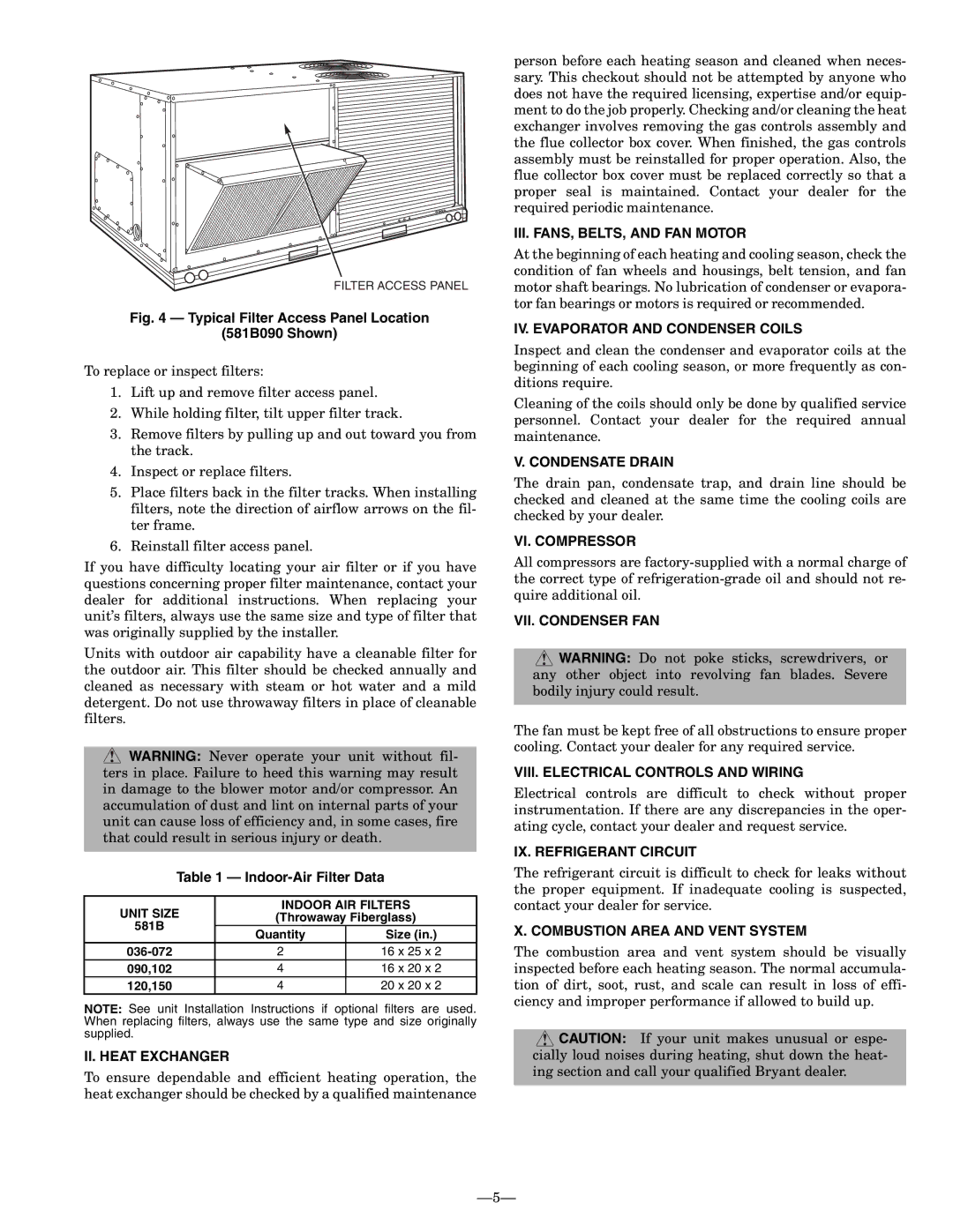
FILTER ACCESS PANEL

Fig. 4 — Typical Filter Access Panel Location

(581B090 Shown)

To replace or inspect filters:

1.Lift up and remove filter access panel.

2.While holding filter, tilt upper filter track.

3.Remove filters by pulling up and out toward you from the track.

4.Inspect or replace filters.

5.Place filters back in the filter tracks. When installing filters, note the direction of airflow arrows on the fil- ter frame.

6.Reinstall filter access panel.

If you have difficulty locating your air filter or if you have questions concerning proper filter maintenance, contact your dealer for additional instructions. When replacing your unit’s filters, always use the same size and type of filter that was originally supplied by the installer.

Units with outdoor air capability have a cleanable filter for the outdoor air. This filter should be checked annually and cleaned as necessary with steam or hot water and a mild detergent. Do not use throwaway filters in place of cleanable filters.

WARNING: Never operate your unit without fil- ters in place. Failure to heed this warning may result in damage to the blower motor and/or compressor. An accumulation of dust and lint on internal parts of your unit can cause loss of efficiency and, in some cases, fire that could result in serious injury or death.

Table 1 — Indoor-Air Filter Data

UNIT SIZE

INDOOR AIR FILTERS

(Throwaway Fiberglass)

581B

Quantity

Size (in.)


036-072

2

16 x 25 x 2

090,102

4

16 x 20 x 2

120,150

4

20 x 20 x 2

NOTE: See unit Installation Instructions if optional filters are used. When replacing filters, always use the same type and size originally supplied.

II. HEAT EXCHANGER

To ensure dependable and efficient heating operation, the heat exchanger should be checked by a qualified maintenance

person before each heating season and cleaned when neces- sary. This checkout should not be attempted by anyone who does not have the required licensing, expertise and/or equip- ment to do the job properly. Checking and/or cleaning the heat exchanger involves removing the gas controls assembly and the flue collector box cover. When finished, the gas controls assembly must be reinstalled for proper operation. Also, the flue collector box cover must be replaced correctly so that a proper seal is maintained. Contact your dealer for the required periodic maintenance.

III. FANS, BELTS, AND FAN MOTOR

At the beginning of each heating and cooling season, check the condition of fan wheels and housings, belt tension, and fan motor shaft bearings. No lubrication of condenser or evapora- tor fan bearings or motors is required or recommended.

IV. EVAPORATOR AND CONDENSER COILS

Inspect and clean the condenser and evaporator coils at the beginning of each cooling season, or more frequently as con- ditions require.

Cleaning of the coils should only be done by qualified service personnel. Contact your dealer for the required annual maintenance.

V. CONDENSATE DRAIN

The drain pan, condensate trap, and drain line should be checked and cleaned at the same time the cooling coils are checked by your dealer.

VI. COMPRESSOR

All compressors are factory-supplied with a normal charge of the correct type of refrigeration-grade oil and should not re- quire additional oil.

VII. CONDENSER FAN

WARNING: Do not poke sticks, screwdrivers, or any other object into revolving fan blades. Severe bodily injury could result.

The fan must be kept free of all obstructions to ensure proper cooling. Contact your dealer for any required service.

VIII. ELECTRICAL CONTROLS AND WIRING

Electrical controls are difficult to check without proper instrumentation. If there are any discrepancies in the oper- ating cycle, contact your dealer and request service.

IX. REFRIGERANT CIRCUIT

The refrigerant circuit is difficult to check for leaks without the proper equipment. If inadequate cooling is suspected, contact your dealer for service.

X. COMBUSTION AREA AND VENT SYSTEM

The combustion area and vent system should be visually inspected before each heating season. The normal accumula- tion of dirt, soot, rust, and scale can result in loss of effi- ciency and improper performance if allowed to build up.

CAUTION: If your unit makes unusual or espe- cially loud noises during heating, shut down the heat- ing section and call your qualified Bryant dealer.

5

Page 5
Image 5
Bryant OM11-19 II. Heat Exchanger, III. FANS, BELTS, and FAN Motor, IV. Evaporator and Condenser Coils, Condensate Drain

OM11-19 specifications

The Bryant OM11-19 is an innovative piece of equipment designed for optimal performance and efficiency in various applications. Known for its reliability and advanced features, the OM11-19 stands out in the market.

One of the main features of the Bryant OM11-19 is its robust design. The construction is engineered to endure harsh conditions, making it suitable for both indoor and outdoor use. Its durable materials ensure longevity, which significantly reduces maintenance costs over time.

Equipped with a state-of-the-art energy management system, the OM11-19 excels in energy efficiency. This feature not only minimizes operational costs but also supports sustainability efforts. The system continuously monitors energy consumption and adjusts operational parameters accordingly, ensuring that energy use is optimized without compromising performance.

Another notable aspect is its intuitive control interface. The Bryant OM11-19 features advanced digital controls that provide users with straightforward operation and easy programming capabilities. This user-friendly interface facilitates quick adjustments and real-time monitoring, ensuring peak performance at all times.

The OM11-19 is also designed with versatility in mind. It is compatible with various attachments and upgrades, allowing users to customize the equipment to better fit their specific needs. This adaptability makes it a favored choice across different industries, including construction, manufacturing, and logistics.

Safety is a top priority in the design of the OM11-19. It comes equipped with several safety features such as overheat protection, automatic shut-off, and emergency stop functions. These systems are designed to protect both the equipment and users, creating a safe working environment.

In terms of technology, the Bryant OM11-19 incorporates the latest advancements in automation and sensor technology. These integrated systems enhance operational reliability and performance. Users benefit from real-time data analytics, allowing them to make informed decisions quickly.

In summary, the Bryant OM11-19 is a highly efficient and versatile piece of equipment that combines durability, advanced technology, and user-friendly features. Its robust design, energy management system, and focus on safety make it an attractive option for a variety of applications, delivering outstanding performance in any setting. Whether for industrial use or more specialized applications, the OM11-19 stands out as a competitive and reliable choice in the market.