Installation and Start-Up Instructions
EVOLUTION NETWORK INTERFACE MODULE
SYSTXBBNIM01
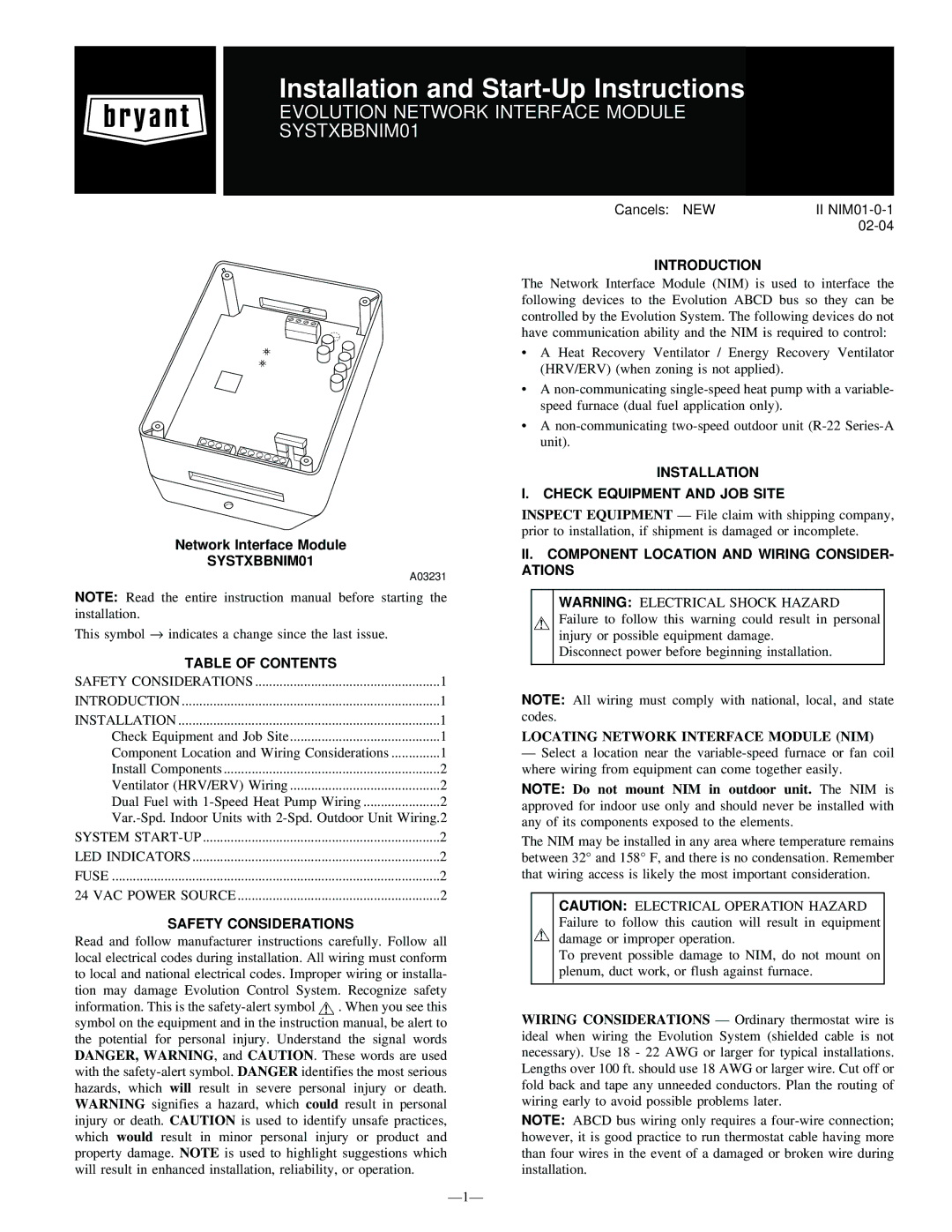
Network Interface Module
SYSTXBBNIM01
A03231
NOTE: Read the entire instruction manual before starting the installation.
This symbol → indicates a change since the last issue.
TABLE OF CONTENTS |
|
SAFETY CONSIDERATIONS | 1 |
INTRODUCTION | 1 |
INSTALLATION | 1 |
Check Equipment and Job Site | 1 |
Component Location and Wiring Considerations | 1 |
Install Components | 2 |
Ventilator (HRV/ERV) Wiring | 2 |
Dual Fuel with | 2 |
SYSTEM | 2 |
LED INDICATORS | 2 |
FUSE | 2 |
24 VAC POWER SOURCE | 2 |
SAFETY CONSIDERATIONS
Read and follow manufacturer instructions carefully. Follow all local electrical codes during installation. All wiring must conform to local and national electrical codes. Improper wiring or installa- tion may damage Evolution Control System. Recognize safety information. This is the ![]() . When you see this symbol on the equipment and in the instruction manual, be alert to the potential for personal injury. Understand the signal words DANGER, WARNING, and CAUTION. These words are used with the
. When you see this symbol on the equipment and in the instruction manual, be alert to the potential for personal injury. Understand the signal words DANGER, WARNING, and CAUTION. These words are used with the
Cancels: NEW | II |
|
INTRODUCTION
The Network Interface Module (NIM) is used to interface the following devices to the Evolution ABCD bus so they can be controlled by the Evolution System. The following devices do not have communication ability and the NIM is required to control:
•A Heat Recovery Ventilator / Energy Recovery Ventilator (HRV/ERV) (when zoning is not applied).
•A
•A
INSTALLATION
I. CHECK EQUIPMENT AND JOB SITE
INSPECT EQUIPMENT — File claim with shipping company, prior to installation, if shipment is damaged or incomplete.
II.COMPONENT LOCATION AND WIRING CONSIDER- ATIONS
WARNING: ELECTRICAL SHOCK HAZARD Failure to follow this warning could result in personal injury or possible equipment damage.
Disconnect power before beginning installation.
NOTE: All wiring must comply with national, local, and state codes.
LOCATING NETWORK INTERFACE MODULE (NIM)
—Select a location near the
NOTE: Do not mount NIM in outdoor unit. The NIM is approved for indoor use only and should never be installed with any of its components exposed to the elements.
The NIM may be installed in any area where temperature remains between 32° and 158° F, and there is no condensation. Remember that wiring access is likely the most important consideration.
CAUTION: ELECTRICAL OPERATION HAZARD Failure to follow this caution will result in equipment damage or improper operation.
To prevent possible damage to NIM, do not mount on plenum, duct work, or flush against furnace.
WIRING CONSIDERATIONS — Ordinary thermostat wire is ideal when wiring the Evolution System (shielded cable is not necessary). Use 18 - 22 AWG or larger for typical installations. Lengths over 100 ft. should use 18 AWG or larger wire. Cut off or fold back and tape any unneeded conductors. Plan the routing of wiring early to avoid possible problems later.
NOTE: ABCD bus wiring only requires a