CONTENTS, DESCRIPTION & ASSEMBLY INSTRUCTIONS
Before proceeding with assembly of powered docking cradle, check the contents of | STEP 2 |
|
| Pass |
|
| Washer For | ||||||||
package to make certain all parts are included. If any parts are missing, please | Model | Serial | Power | PCB Washer | |||||||||||
Through | Nut | ||||||||||||||
contact NPI for a replacement part at: |
|
| h1900 | NO | NO | NO | NA | NA | |||||||
A |
|
|
|
|
|
|
|
| h2200 | YES | YES | YES | WHITE, BLACK | BLUE, RED | |
|
|
|
| A. 1 qty. RAM Main Plastic Housing |
| hx2415 | YES | YES | YES | WHITE, BLUE, | GREEN | ||||
|
|
|
|
|
| RED | |||||||||
|
|
| B |
| B. 1 qty. RAM PCB Plastic Cover |
| rx3115 | YES | NO | YES | WHITE, BLUE | GREEN | |||
|
|
|
| C. 1 qty. Input / Output Printed Circuit |
| 3650 | NO | NO | NO | NA | NA | ||||
|
|
|
|
|
|
| DATA YES, |
|
| WHITE, | |||||
|
|
|
|
| Board |
|
| 3955 | YES | YES | RED | ||||
|
|
|
|
|
|
| POWER NO | GREEN, BLUE | |||||||
|
|
|
| F | D. 1 qty. Power Printed Circuit Board |
| h4100 | YES | YES | YES | WHITE, BLACK, | BLUE | |||
|
|
|
| E. 1 qty. IPAQ Male Connector Printed |
| RED | |||||||||
|
|
|
|
| h4300 | YES | YES | YES | WHITE, BLUE | ||||||
|
|
|
|
| Circuit Board |
|
| GREEN, RED | |||||||
|
|
|
|
|
|
| hx4700 | YES | YES | YES | GREEN | WHITE, BLUE | |||
|
|
|
|
| F. 1 qty. each Null Modem Wire |
| h5555 | YES | YES | YES | RED | WHITE, | |||
|
|
|
|
| Harness (RED), |
|
|
|
|
|
| GREEN, BLUE | |||
|
|
|
|
|
| h6315 | NO | YES | YES | WHITE | GREEN | ||||
|
|
|
|
| Harness (BLACK), |
|
| ||||||||
|
|
|
|
|
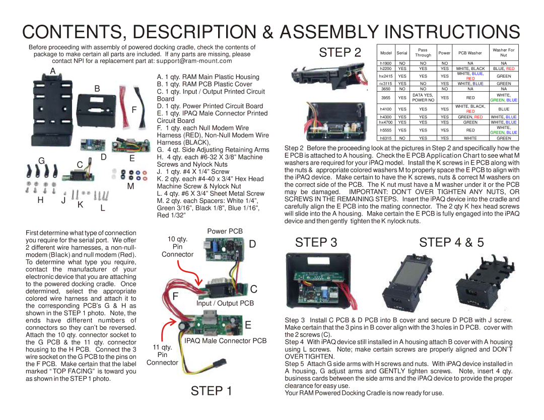
| Step 2 Before the proceeding look at the pictures in Step 2 and specifically how the | |||||||||
|
|
|
|
| G. | 4 qt. Side Adjusting Retaining Arms | |||||||||
G |
|
| D | E | H. | 4 qty. each | E PCB is attached to A housing. Check the E PCB Application Chart to see what M | ||||||||
| C | Screws and Nylock Nuts |
| washers are required for your iPAQ model. Install the K screws in E PCB along with | |||||||||||
|
|
|
|
| the nuts & appropriate colored washers M to properly space the E PCB to align with | ||||||||||
|
|
|
|
| J. | 1 qty. #4 X 1/4” Screw |
| ||||||||
|
|
|
| M | K. 2 qty. each | the iPAQ device. Make certain to have the K screws, nuts & correct M washers on | |||||||||
|
|
|
| Machine Screw & Nylock Nut |
| the correct side of the PCB. The K nut must have a M washer under it or the PCB | |||||||||
H | J |
|
|
| L. 4 qty. #6 X 3/4” Sheet Metal Screw | may be damaged. IMPORTANT: DON’T OVER TIGHTEN ANY NUTS, OR | |||||||||
K |
|
| M. 2 qty. each Spacers: White 1/4”, | SCREWS IN THE REMAINING STEPS. Insert the iPAQ device into the cradle and | |||||||||||
|
| L |
| Green 3/16”, Black 1/8”, Blue 1/16”, | carefully align the E PCB into the mating connector. The 2 qty K hex head screws | ||||||||||
|
|
|
| will slide into the A housing. Make certain the E PCB is fully engaged into the iPAQ | |||||||||||
|
|
|
|
| Red 1/32” |
| |||||||||
|
|
|
|
|
|
|
| device and then gently tighten the K nylock nuts. |
|
|
| ||||
First determine what type of connection |
| Power PCB |
| STEP 3 |
|
| STEP 4 & 5 |
| |||||||
you require for the serial port. We offer |
| 10 qty. | D |
|
|
| |||||||||
2 different wire harnesses, a |
| Pin |
|
|
| ||||||||||
modem (Black) and null modem (Red). | Connector |
|
|
|
|
|
|
|
| ||||||
To determine what type you require, |
|
|
|
|
|
|
|
|
|
| |||||
contact the manufacturer of your |
|
|
|
|
|
|
|
|
|
| |||||
electronic device that you are attaching |
|
|
|
|
|
|
|
|
|
| |||||
to the powered docking cradle. Once |
|
| C |
|
|
|
|
|
|
| |||||
determined, | select the appropriate |
| F |
|
|
|
|
|
|
| |||||
colored wire harness and attach it to |
|
|
|
|
|
|
|
|
| ||||||
the corresponding PCB’s G & H as |
| Input / Output PCB |
|
|
|
|
|
|
| ||||||
shown in the STEP 1 photo. Note, the |
|
|
| Step 3 Install C PCB & D PCB into B cover and secure D PCB with J screw. | |||||||||||
ends have different numbers of |
|
| E | ||||||||||||
connectors so they can’t be reversed. |
|
| Make certain that the 3 pins in B cover align with the 3 holes in D PCB. cover with | ||||||||||||
Attach the 10 qty. connector socket to |
| IPAQ Male Connector PCB | the 2 screws (C). |
|
|
|
|
|
| ||||||
the G PCB & the 11 qty. connector |
| Step 4 With iPAQ device still installed in A housing attach B cover with A housing | |||||||||||||
housing to the H PCB. Connect the 3 | 11 qty. |
| using L screws. Note; make certain screws are properly aligned and DON’T | ||||||||||||
wire socket on the G PCB to the pins on | Pin |
| OVER TIGHTEN. |
|
|
|
|
|
| ||||||
the F PCB. Make certain that the label | Connector |
| Step 5 Attach G side arms with H screws and nuts. With iPAQ device installed in | ||||||||||||
marked “TOP FACING” is toward you |
|
|
| A housing, G adjust arms and GENTLY tighten screws. | Note, insert 4 qty. | ||||||||||
as shown in the STEP 1 photo. |
|
|
|
| business cards between the side arms and the iPAQ device to provide the proper | ||||||||||
|
|
|
|
|
| STEP 1 |
| clearance for easy use. |
|
|
|
|
|
| |
|
|
|
|
|
|
| Your RAM Powered Docking Cradle is now ready for use. |
|
| ||||||