875HT specifications
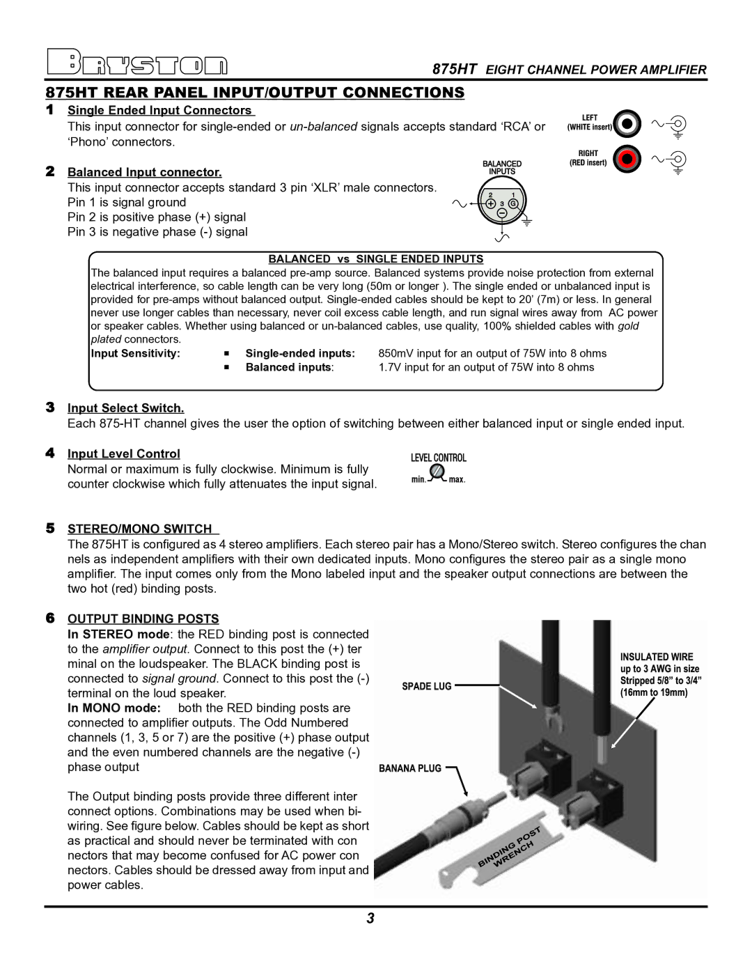
The Bryston 875HT is a high-performance multi-channel power amplifier designed specifically for home theater enthusiasts and audiophiles seeking superior audio fidelity. Bryston, a name synonymous with quality in the audio industry, has engineered the 875HT to deliver exceptional power, clarity, and reliability, making it an ideal choice to drive a multi-channel surround sound system.One of the standout features of the Bryston 875HT is its robust power output. This amplifier is capable of delivering an impressive 120 watts per channel into 8 ohms and 200 watts per channel into 4 ohms across up to seven channels. This ensures that even the most demanding audio environments are handled with ease, providing dynamic headroom for explosive sound effects and intricately nuanced music tracks.
The 875HT incorporates Bryston's proprietary technology, including its innovative circuitry and high-quality components. All Bryston amplifiers are built with fully discrete circuitry, which significantly enhances sound reproduction and reduces distortion. Additionally, the 875HT features a toroidal power transformer, renowned for its efficiency and low electromagnetic interference, ensuring pristine signal integrity throughout the audio spectrum.
Thermal management is another critical aspect of the 875HT’s design. It employs a large, custom-designed heat sink that allows for efficient heat dissipation, ensuring the amplifier remains cool even during extended play. This reliability not only preserves the lifespan of the components but also maintains consistent performance levels across various operating conditions.
The aesthetics of the Bryston 875HT also do not go unnoticed. With its robust, all-metal construction and a classic, minimalist design, it can seamlessly integrate into any home theater system. It is available in various finishes, allowing users to choose a look that best matches their décor.
Moreover, the 875HT is backed by Bryston's renowned 20-year warranty, a testament to the manufacturer's confidence in the durability and performance of this amplifier. The ability to connect multiple sources, along with its efficient architecture, positions the Bryston 875HT as a formidable competitor in the multi-channel amplifier market.
Overall, the Bryston 875HT exemplifies audio excellence, embodying high power, advanced engineering, and a commitment to immersive sound quality, making it a perfect centerpiece for any high-end home theater setup.

