Commercial Snowblower
ASSEMBLY INSTRUCTIONS – cont’d.
b)Using tape or a bright colored marking pen, mark on the outer shields the position where the shaft is completely pushed together and the position where you have a 4” overlap. Watch these marks when moving the blower through all possible operating angles to see that the PTO shaft stays within this range.
c)With the engine on the tractor shut off, attach the PTO shaft. The tractor end has a standard
![]() Caution: Always check to see that both ends of the PTO shaft are securely attached every time the Snowblower is used. This should always be done with the tractor engine off.
Caution: Always check to see that both ends of the PTO shaft are securely attached every time the Snowblower is used. This should always be done with the tractor engine off.
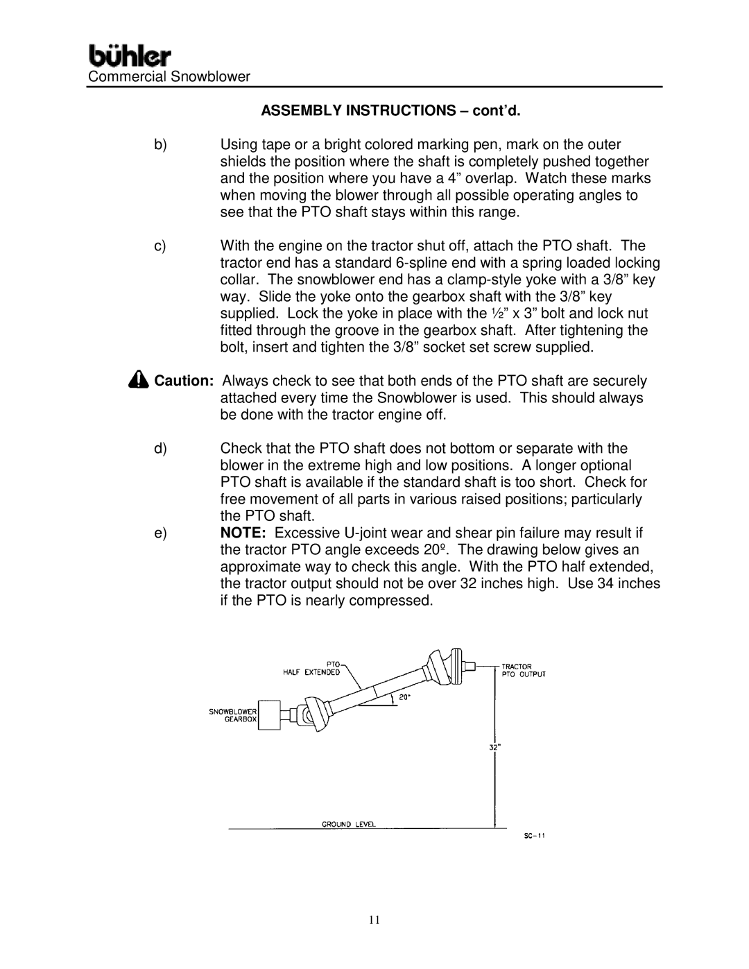
d)Check that the PTO shaft does not bottom or separate with the blower in the extreme high and low positions. A longer optional PTO shaft is available if the standard shaft is too short. Check for free movement of all parts in various raised positions; particularly the PTO shaft.
e)NOTE: Excessive
11