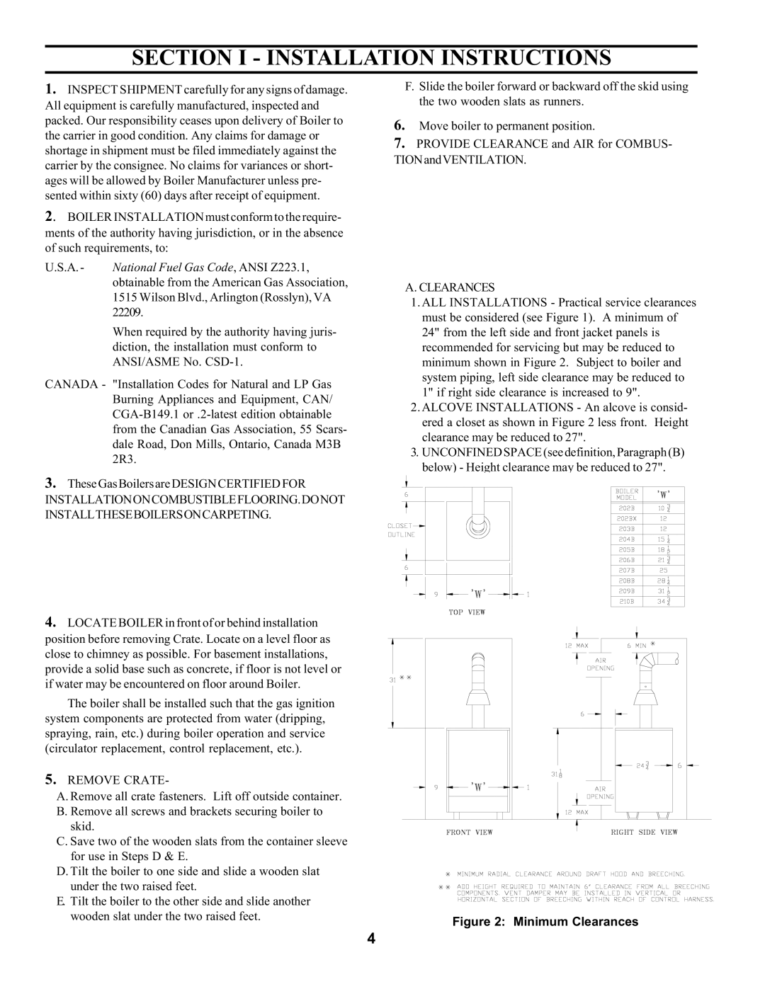
Figure 2: Minimum Clearances

SECTION I - INSTALLATION INSTRUCTIONS

1. INSPECT SHIPMENT carefully for any signs of damage.

F. Slide the boiler forward or backward off the skid using

All equipment is carefully manufactured, inspected and

the two wooden slats as runners.


packed. Our responsibility ceases upon delivery of Boiler to

6. Move boiler to permanent position.

the carrier in good condition. Any claims for damage or

7. PROVIDE CLEARANCE and AIR for COMBUS-

shortage in shipment must be filed immediately against the

TIONandVENTILATION.

carrier by the consignee. No claims for variances or short-


ages will be allowed by Boiler Manufacturer unless pre-


sented within sixty (60) days after receipt of equipment.


2. BOILER INSTALLATION must conform to the require-


ments of the authority having jurisdiction, or in the absence


of such requirements, to:


U.S.A. -

National Fuel Gas Code, ANSI Z223.1,


obtainable from the American Gas Association,

A. CLEARANCES


1515 Wilson Blvd., Arlington (Rosslyn), VA


1. ALL INSTALLATIONS - Practical service clearances


22209.


must be considered (see Figure 1). A minimum of


When required by the authority having juris-

24" from the left side and front jacket panels is


diction, the installation must conform to

recommended for servicing but may be reduced to


ANSI/ASME No. CSD-1.

minimum shown in Figure 2. Subject to boiler and

CANADA -

"Installation Codes for Natural and LP Gas

system piping, left side clearance may be reduced to

1" if right side clearance is increased to 9".


Burning Appliances and Equipment, CAN/

CGA-B149.1 or .2-latest edition obtainable

2. ALCOVE INSTALLATIONS - An alcove is consid-

ered a closet as shown in Figure 2 less front. Height

from the Canadian Gas Association, 55 Scars-

clearance may be reduced to 27".

dale Road, Don Mills, Ontario, Canada M3B

3. UNCONFINED SPACE (see definition, Paragraph (B)

2R3.

below) - Height clearance may be reduced to 27".


3.These Gas Boilers are DESIGN CERTIFIED FOR

INSTALLATIONONCOMBUSTIBLEFLOORING.DONOT

INSTALLTHESEBOILERSONCARPETING.

4.LOCATE BOILER in front of or behind installation

position before removing Crate. Locate on a level floor as close to chimney as possible. For basement installations, provide a solid base such as concrete, if floor is not level or if water may be encountered on floor around Boiler.

The boiler shall be installed such that the gas ignition system components are protected from water (dripping, spraying, rain, etc.) during boiler operation and service (circulator replacement, control replacement, etc.).

5.REMOVE CRATE-

A. Remove all crate fasteners. Lift off outside container. B. Remove all screws and brackets securing boiler to

skid.

C. Save two of the wooden slats from the container sleeve for use in Steps D & E.

D. Tilt the boiler to one side and slide a wooden slat under the two raised feet.

E. Tilt the boiler to the other side and slide another wooden slat under the two raised feet.

4

Page 4
Image 4
Burnham SERIES 2 manual Clearances, Canada, Remove Crate

SERIES 2 specifications

The Burnham SERIES 2 is a highly regarded addition to the lineup of residential and commercial heating systems, known for its efficiency, reliability, and innovative design. Designed with the user in mind, the SERIES 2 boasts a range of main features that cater to the needs of modern heating solutions.

One of the standout characteristics of the Burnham SERIES 2 is its advanced cast iron construction. This material is renowned for its durability and excellent heat retention capabilities, ensuring that the system provides consistent warmth over extended periods. The cast iron heat exchanger allows for efficient heat transfer and maximizes energy output while minimizing heat loss.

Efficiency is a key focus for the Burnham SERIES 2, and it is designed to operate at high annual fuel utilization efficiency (AFUE) ratings. With its efficiency-enhancing features, including advanced combustion technology, the system helps homeowners save on energy costs while reducing their environmental footprint. The SERIES 2’s design helps ensure that a greater percentage of the fuel consumed is converted into usable heat, making it a smart choice for energy-conscious users.

Another significant feature is the versatile configuration options available with the Burnham SERIES 2. It can be installed in various settings, including basements, utility rooms, or even garages, due to its compact design. The system is compatible with multiple fuel types, allowing users to select between natural gas and propane to suit their specific preferences and availability.

The Burnham SERIES 2 also prioritizes ease of maintenance. Its user-friendly design includes access panels that simplify servicing and routine inspections. Additionally, it incorporates a range of safety features, such as an automatic shut-off system and built-in controls, to ensure safe operation.

In terms of technology, the SERIES 2 utilizes an innovative control system that optimizes heating cycles based on user demands and external conditions. This intelligent control enhances comfort and prevents excessive cycling, thereby prolonging the lifespan of the unit.

Overall, the Burnham SERIES 2 is distinguished by its robust construction, energy-efficient operation, versatility in installation, ease of maintenance, and advanced technology. For homeowners and businesses seeking a reliable heating solution, it represents a compelling choice, delivering warmth and comfort while remaining mindful of energy consumption and environmental impact.