
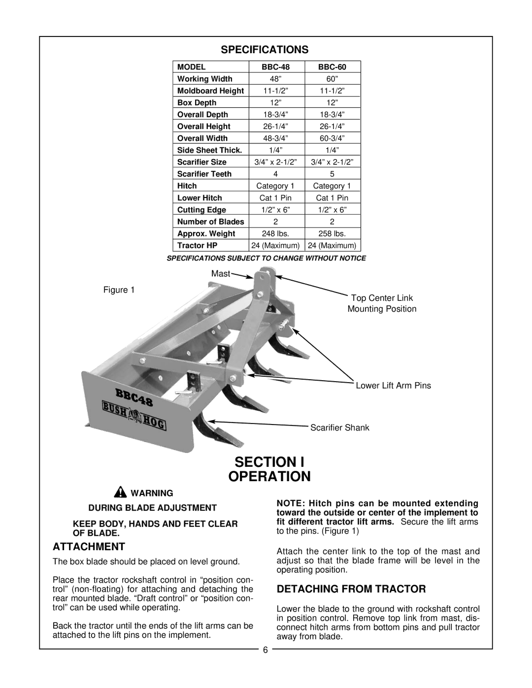
BBC 48, BBC 60 specifications
Bush Hog is a renowned name in the world of land management and agricultural equipment, and their BBC (Brush Cutter) series, specifically the BBC 48 and BBC 60 models, exemplifies their commitment to quality and performance. These rugged machines are designed to tackle heavy brush, grass, and overgrown vegetation, making them indispensable tools for property maintenance and land clearing tasks.The Bush Hog BBC 48 and BBC 60 are both equipped with powerful engines that deliver reliable performance across a variety of terrains. The BBC 48 features a 48-inch cutting width, whereas the BBC 60 boasts a 60-inch cutting width, allowing users to select the model that best suits their specific land management needs. Both models are built with a robust construction that ensures durability and longevity, allowing them to withstand the rigors of demanding environments.
A key feature of the Bush Hog BBC series is their heavy-duty gear drive transmission. This technology provides superior torque and power transfer, enabling the brush cutters to handle thick brush and thick weed growth efficiently. The reinforced blades are designed to maintain sharpness longer and endure tough cutting conditions, which translates into fewer maintenance interruptions.
Safety is a major concern, and Bush Hog addresses this with several integrated safety features. Both the BBC 48 and BBC 60 come equipped with guards and shields that protect the operator against flying debris. Additionally, the machines are designed with operator-friendly controls, making it easier for users to navigate and operate the equipment safely.
Another notable characteristic of the Bush Hog BBC series is their maneuverability. With their compact design and excellent weight distribution, these brush cutters can easily navigate tight spaces and steep terrains, ensuring users can access even the most challenging areas on their properties. Whether managing large estates, farmland, or rural properties, the BBC 48 and BBC 60 models provide efficient solutions for maintaining clear and safe land.
In summary, the Bush Hog BBC 48 and BBC 60 brush cutters are exceptional tools for anyone needing to manage brush and overgrowth. Their powerful engines, heavy-duty construction, advanced gear drive technology, and safety features make them trusted choices for landowners and professionals alike. With these models, users can expect reliable performance and the ability to tackle the toughest jobs with ease. Whether for routine maintenance or larger land-clearing projects, Bush Hog’s BBC series promises efficient and effective results.