D. Loosely attach two caster arms to the front of the mower deck using 5/8 x
E. Fasten mast supports and upper flex link to mast halves using 1/2 x 5” capscrew, pivot tube and locknut..
F. Place two long spacers on the caster stems and insert into caster arms. Place two long spacers and two short spacers on the caster stem above the caster arms. This arrangement will give a cutting height of approximately three inches. Secure with lynch pin retainers. With weight of cutter resting on all four wheels, ensure that cutter is level. Tighten all bolts on mounting brackets.
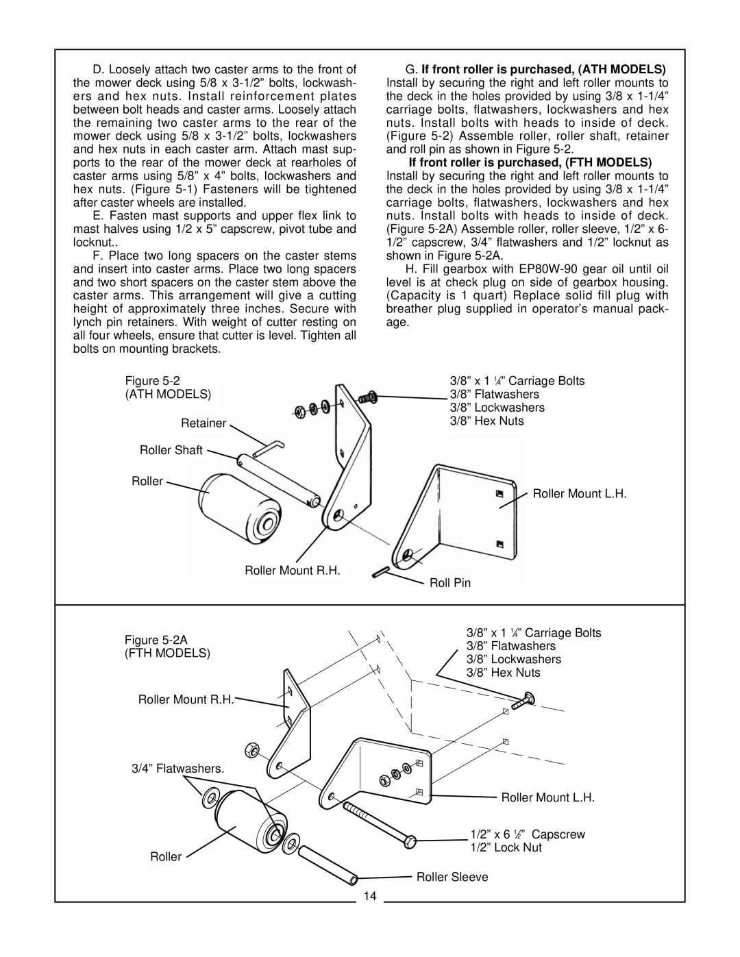
Figure
(ATH MODELS)
Retainer
Roller Shaft
Roller
Roller Mount R.H.
G. If front roller is purchased, (ATH MODELS) Install by securing the right and left roller mounts to the deck in the holes provided by using 3/8 x
If front roller is purchased, (FTH MODELS) Install by securing the right and left roller mounts to the deck in the holes provided by using 3/8 x
H. Fill gearbox with
3/8” x 1 1⁄4” Carriage Bolts
3/8” Flatwashers
3/8” Lockwashers
3/8” Hex Nuts
Roller Mount L.H.
![]() Roll Pin
Roll Pin
Figure 5-2A
(FTH MODELS)
Roller Mount R.H.
![]()
![]()
3/8” x 1 1⁄4” Carriage Bolts
3/8” Flatwashers
3/8” Lockwashers
3/8” Hex Nuts
3/4” Flatwashers. ![]()
![]()
![]()
![]()
![]()
![]()
![]()
![]()
![]()
![]()
![]()
![]()
![]()
![]()
![]()
![]()
![]()
![]() Roller Mount L.H.
Roller Mount L.H.
|
| 1/2” x 6 | 1⁄2” Capscrew |
Roller |
| 1/2” Lock Nut | |
| Roller Sleeve |
| |
| 14 |
| |
|
|
| |