GC-250 specifications
The Bush Hog GC-250 is a versatile and robust piece of equipment designed for both homeowners and professionals seeking efficient land management solutions. This compact tractor is renowned for its ability to handle a variety of tasks, making it an ideal choice for those requiring a reliable machine for maintenance and landscaping duties.One of the standout features of the GC-250 is its powerful engine. Equipped with a dynamic, fuel-efficient diesel engine, this tractor delivers impressive torque and power while maintaining excellent fuel economy. This means users can tackle tough jobs without the worry of frequent refueling, making it perfect for extended workday projects.
The GC-250 boasts a user-friendly design, highlighted by its comfortable operator station. The ergonomically designed seat, intuitive controls, and spacious layout contribute to an enjoyable work experience. Additionally, the tractor's compact size enhances maneuverability, allowing it to navigate tight spaces and uneven terrain with ease.
Another key characteristic of the Bush Hog GC-250 is its durability. Built with high-quality materials and advanced manufacturing processes, this tractor is designed to withstand harsh conditions and heavy use. The robust frame and high-strength components ensure longevity, making it a reliable investment for years to come.
The GC-250 also features a well-engineered hydraulic system, providing impressive lifting power. This enhances the tractor's ability to handle various attachments, such as loaders, mowers, and backhoes, increasing its versatility. The hydraulic quick-attach system facilitates swift transitions between different attachments, reducing downtime and improving overall efficiency.
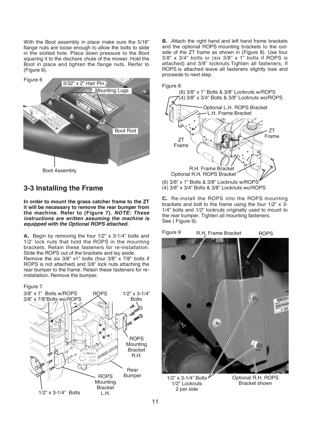
Safety is a fundamental aspect of the design of the Bush Hog GC-250. Features such as a ROPS (Roll-Over Protective Structure) and safety interlocks are incorporated to protect the operator during operation. The visibility from the operator station is optimized, allowing for better awareness of surroundings, which is vital in preventing accidents.
In conclusion, the Bush Hog GC-250 stands out as a reliable, efficient, and versatile tractor suitable for a range of applications. With its powerful engine, user-friendly design, durable construction, advanced hydraulic system, and built-in safety features, it is an excellent choice for anyone looking to enhance their land maintenance capabilities. Whether for residential use, small farms, or landscaping projects, the GC-250 offers impressive performance and value.

