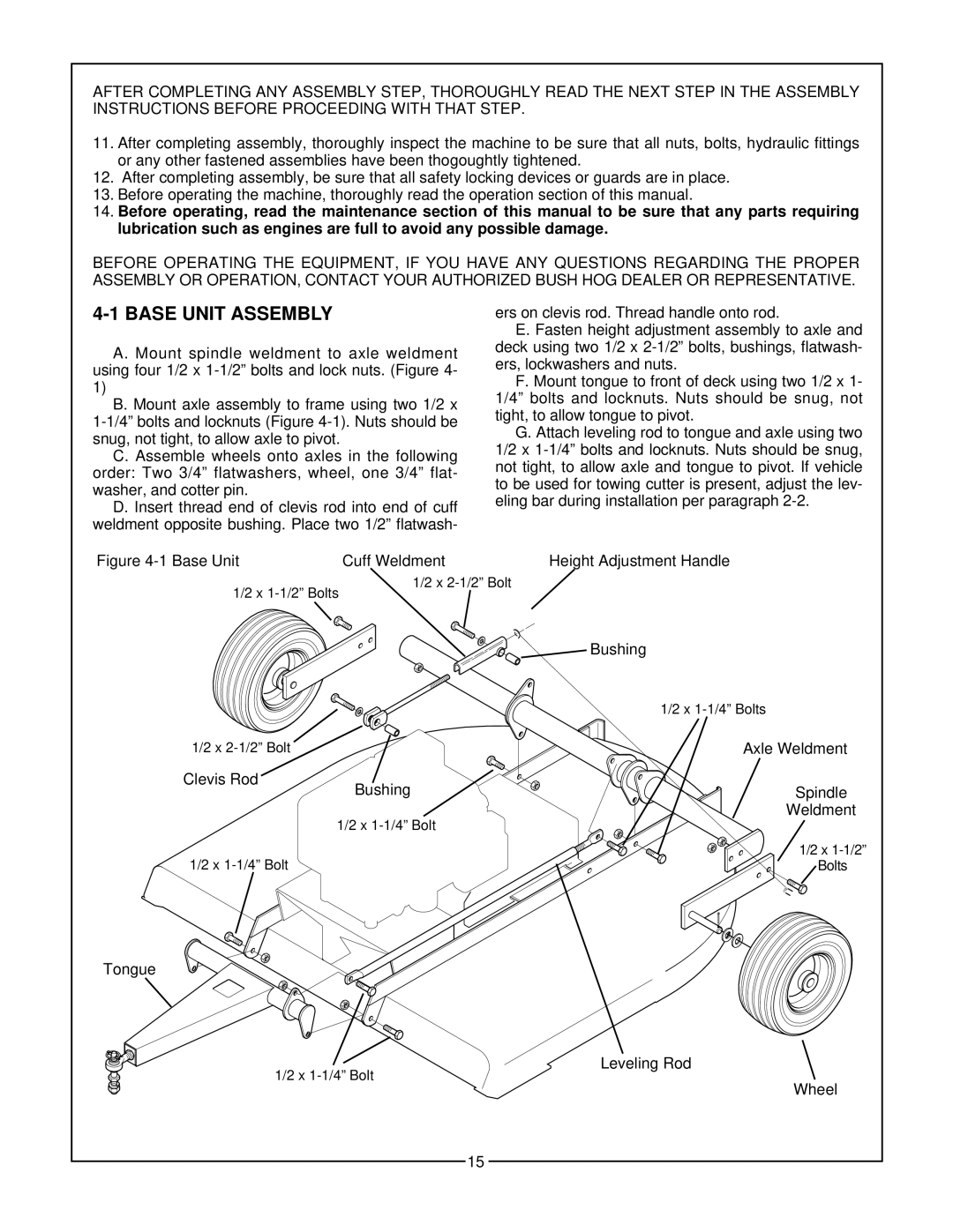
GT 48 specifications
The Bush Hog GT 48 is a highly regarded piece of equipment in the landscaping and agricultural sectors, known for its robust performance and efficiency. Designed with the user in mind, this rotary mower is ideal for maintaining pastures, fields, and large gardens. Its impressive features make it a popular choice among both professionals and hobbyists.One of the main characteristics of the Bush Hog GT 48 is its cutting width of 48 inches. This size strikes an excellent balance between maneuverability and coverage. The unit's heavy-duty construction ensures durability, allowing it to withstand the rigors of demanding mowing tasks. The frame is built from high-strength materials, contributing to its longevity and reliability.
The GT 48 features an adjustable cutting height, enabling users to customize their mowing experience based on the specific needs of their lawn or pasture. The height adjustment is user-friendly, allowing for quick changes without the use of additional tools. This feature ensures that the mower can tackle various grass heights efficiently.
Equipped with a powerful rotary cutting system, the Bush Hog GT 48 delivers a clean and precise cut. Its sharp blades are engineered to provide superior performance, reducing clumping and ensuring an even finish. The mower's design helps in dispersing the grass clippings evenly, promoting healthy lawn growth.
Another significant aspect of the GT 48 is its compatibility with a range of tractors. It is designed to work seamlessly with various models, making it a versatile choice for users with different equipment. This adaptability is further enhanced by its three-point hitch system, which facilitates easy attachment and detachment from the tractor.
Safety features are also a highlight of the Bush Hog GT 48. The mower comes equipped with a shielded design to protect users from flying debris, ensuring a safer mowing experience. The low center of gravity provides stability, reducing the risk of tipping during operation.
In terms of maintenance, the Bush Hog GT 48 is relatively easy to care for. Regular checks on the blades and lubrication of moving parts help prolong its life and efficiency. The unit's straightforward design allows users to complete maintenance tasks with minimal hassle.
Overall, the Bush Hog GT 48 stands out for its blend of power, versatility, and ease of use. Its advanced features make it a solid investment for anyone looking to efficiently manage their mowing needs. Whether for professional or personal use, this mower is designed to deliver results that meet and exceed expectations.

