Chapter 3
Operation
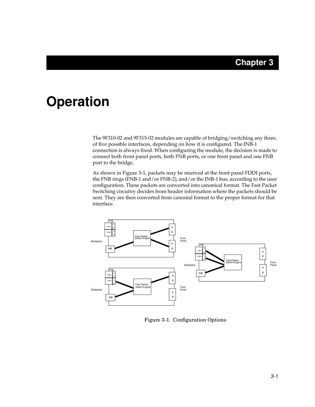
The 9F310-02 and 9F315-02 modules are capable of bridging/switching any three, of five possible interfaces, depending on how it is configured. The INB-1 connection is always fixed. When configuring the module, the decision is made to connect both front panel ports, both FNB ports, or one front panel and one FNB port to the bridge.
As shown in Figure 3-1,packets may be received at the front panel FDDI ports, the FNB rings (FNB-1 and/or FNB-2), and/or the INB-1 bus, according to the user configuration. These packets are converted into canonical format. The Fast Packet Switching circuitry decides from header information where the packets should be sent. They are then converted from canonial format to the proper format for that interface.
FNB
Fast Packet Switch Engine
Fast Packet Switch Engine
Fast Packet Switch Engine
Figure 3-1. Configuration Options
3-1

