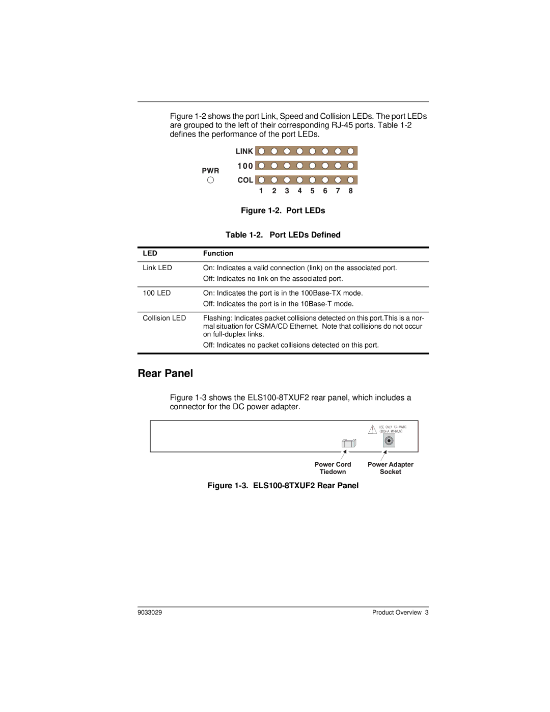
Figure 1-2 shows the port Link, Speed and Collision LEDs. The port LEDs are grouped to the left of their corresponding RJ-45 ports. Table 1-2 defines the performance of the port LEDs.
| Figure |
| Table |
|
|
LED | Function |
|
|
Link LED | On: Indicates a valid connection (link) on the associated port. |
| Off: Indicates no link on the associated port. |
|
|
100 LED | On: Indicates the port is in the |
| Off: Indicates the port is in the |
|
|
Collision LED | Flashing: Indicates packet collisions detected on this port.This is a nor- |
| mal situation for CSMA/CD Ethernet. Note that collisions do not occur |
| on |
| Off: Indicates no packet collisions detected on this port. |
|
|
Rear Panel
Figure 1-3 shows the ELS100-8TXUF2 rear panel, which includes a connector for the DC power adapter.
Figure 1-3. ELS100-8TXUF2 Rear Panel
9033029 | Product Overview 3 |