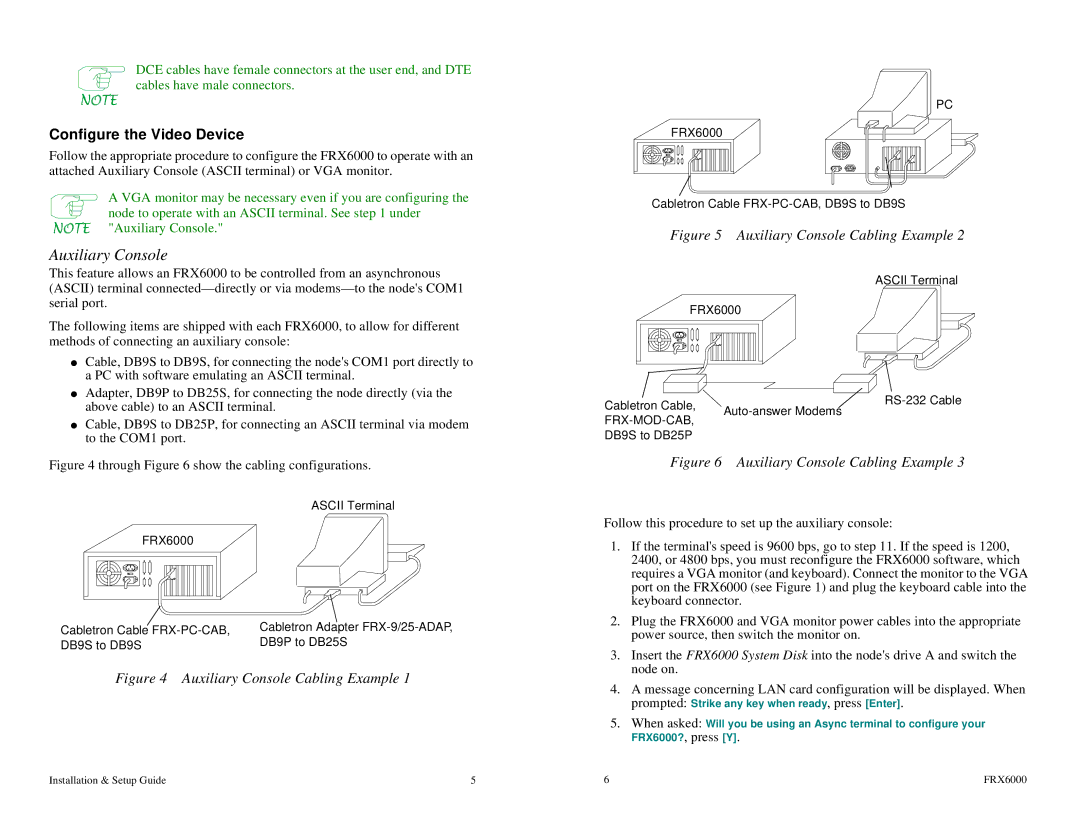
Netlink FRX4000, FRX6000 specifications
Cabletron Systems, a leading player in network management and telecommunications solutions during the late 20th century, introduced several innovative products that played a crucial role in shaping enterprise networking. Among these were the Cabletron FRX6000, FRX4000, and the FRX1800, which delivered advanced features aimed at enhancing network performance, security, and scalability.The Cabletron FRX6000 was designed as a robust multi-layer switch, ideal for large-scale enterprise environments. It supported extensive routing capabilities, allowing organizations to manage traffic efficiently even under heavy loads. The FRX6000 boasted high throughput rates and low latency, making it suitable for demanding applications. With support for various network protocols, including IP, IPX, and AppleTalk, its adaptability made it a versatile choice for diverse networking needs. Moreover, security features like VLAN support and Access Control Lists (ACLs) provided enhanced protection against potential threats.
Moving to the FRX4000, this model offered a balance between performance and cost-effectiveness. The FRX4000 maintained many of the essential features of its larger counterpart while catering to medium-sized enterprises. It provided Layer 3 routing and could handle multiple simultaneous connections, ensuring seamless communication across departments. The modular design allowed for easy upgrades, enabling businesses to expand their network infrastructure without significant overhauls. This made the FRX4000 an attractive option for organizations looking to optimize their network investments.
Lastly, the FRX1800, designed for small to medium businesses, focused on simplicity and ease of use while still incorporating powerful network management capabilities. Its user-friendly interface made it accessible for organizations lacking extensive IT resources. The FRX1800 provided essential functionalities such as Integrated Layer 2 switching and routing, network monitoring, and basic security features, ensuring that even smaller companies could maintain efficient, reliable networking without overwhelming complexity.
All three models utilized advanced technologies, including a high bandwidth backbone and state-of-the-art switching architecture, to enable fast and reliable data transfer. They also supported Quality of Service (QoS) mechanisms, allowing businesses to prioritize critical applications and ensure consistent performance across the network.
In summary, the Cabletron FRX6000, FRX4000, and FRX1800 were pivotal in enhancing network capabilities, providing organizations with scalable, secure, and high-performance options tailored to their specific needs.

