KBU64 Rackmount User Manual
2.2.4 X21 Rear Interface Card
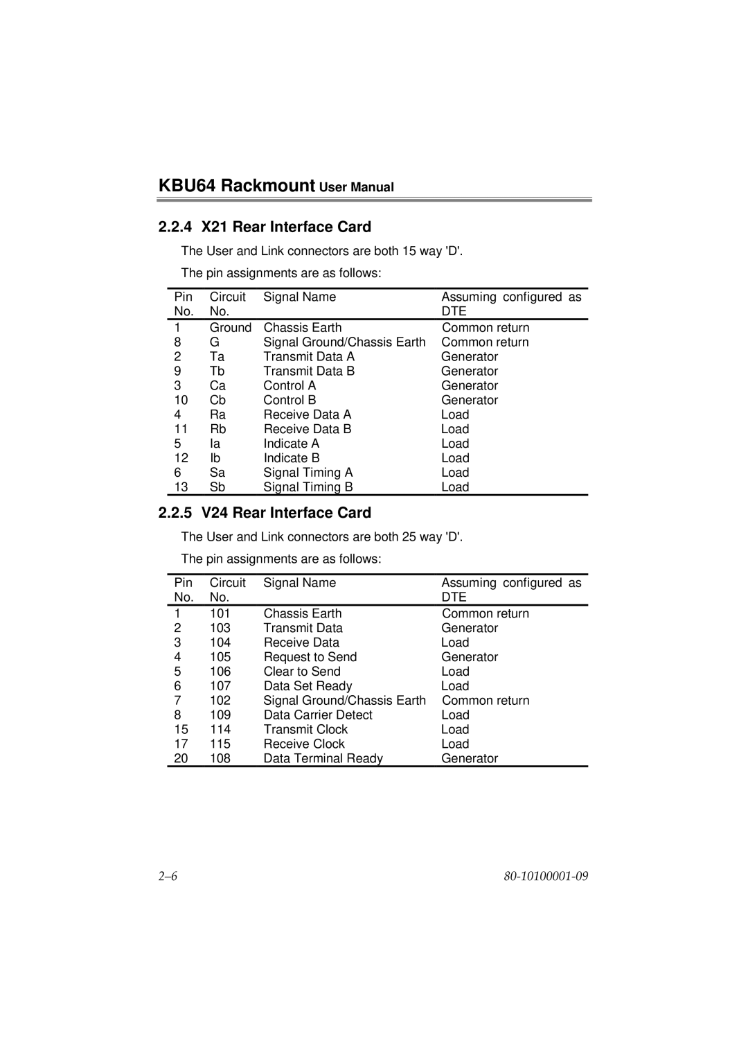
The User and Link connectors are both 15 way 'D'.
The pin assignments are as follows:
Pin | Circuit | Signal Name | Assuming configured as |
No. | No. |
| DTE |
1 | Ground | Chassis Earth | Common return |
8 | G | Signal Ground/Chassis Earth | Common return |
2 | Ta | Transmit Data A | Generator |
9 | Tb | Transmit Data B | Generator |
3 | Ca | Control A | Generator |
10 | Cb | Control B | Generator |
4 | Ra | Receive Data A | Load |
11 | Rb | Receive Data B | Load |
5 | Ia | Indicate A | Load |
12 | Ib | Indicate B | Load |
6 | Sa | Signal Timing A | Load |
13 | Sb | Signal Timing B | Load |
2.2.5 V24 Rear Interface Card
The User and Link connectors are both 25 way 'D'.
The pin assignments are as follows:
Pin | Circuit | Signal Name | Assuming configured as |
No. | No. |
| DTE |
1 | 101 | Chassis Earth | Common return |
2 | 103 | Transmit Data | Generator |
3 | 104 | Receive Data | Load |
4 | 105 | Request to Send | Generator |
5 | 106 | Clear to Send | Load |
6 | 107 | Data Set Ready | Load |
7 | 102 | Signal Ground/Chassis Earth | Common return |
8 | 109 | Data Carrier Detect | Load |
15 | 114 | Transmit Clock | Load |
17 | 115 | Receive Clock | Load |
20 | 108 | Data Terminal Ready | Generator |
