READ ALL

INSTRUCTIONS

AND SAFETY

INFORMATION.

WARNING! Risk of electrical shock. Turn off all power at the electrical panel board supplying power to the heater before doing any electrical wiring.

WARNING! Do not hit or damage the temperature limit

sensing switch on this heater.

WARNING! Do not operate the heater without the front cover in place.

IMPORTANT! It is extremely important that you verify the electrical supply wires are the same voltage as the heater (i.e. 120 volt heater to 120 volt power supply and 240 volt heater to 240 volt power supply).

Installation Instructions

1.Remove the heater front panel by lifting up and pulling out on the bottom edge of the front panel. Set the front panel aside.

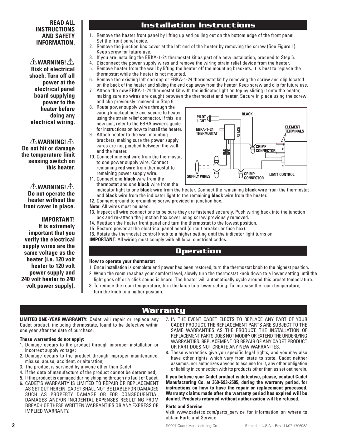
2.Remove the junction box cover at the left end of the heater by removing the screw (See Figure 1). Keep screw for future use.

3.If you are installing the EBKA-1-24 thermostat kit as part of a new installation, proceed to Step 6.

4.Disconnect the power supply wires and remove the wiring strain relief device from the heater.

5.Remove heater from the wall by lifting the heater off the mounting brackets. It is best to replace the thermostat while the heater is not mounted.

6.Remove the existing left end cap or EBKA-1-24 thermostat kit by removing the screw and clip located on the back of the heater and sliding the end cap away from the heater. Keep screw and clip for future use.

7.Attach the new EBKA-1-24 thermostat kit with the indicator light on top by sliding it onto the heater, making sure no wires are caught between the thermostat and heater. Secure in place using the screw and clip previously removed in Step 6.

8.Route power supply wires through the


wiring knockout hole and secure to heater

PILOT


BLACK


using the strain relief connector. If this is a


new unit, refer to the EBHA owner’s guide

LIGHT


BLACK


ELEMENT


for instructions on how to install the heater.

EBKA-1-24


9.

Attach heater to the wall mounting

THERMOSTAT


TERMINALS


brackets, making sure the power supply


wires are not pinched between the wall


RED RED


CRIMP


and the heater.


CONNECTOR


10.

Connect one red wire from the thermostat


to one power supply wire. Connect


remaining red wire from thermostat to


remaining power supply wire.


CRIMP

LIMIT

CONTROL


SUPPLY WIRES


11.

Connect one black wire from the


CONNECTOR


thermostat and one black wire from the


indicator light to one black wire from the heater. Connect the remaining black wire from the thermostat


and black wire from the indicator light to the remaining black wire from the heater.


12.Connect ground to grounding screw provided in junction box. Note: All wires must be used.

13.Inspect all wire connections to be sure they are fastened securely. Push wiring back into the junction box and re-attach the junction box cover using screw previously removed.

14.Reattach the heater front panel and turn the thermostat to the lowest position.

15.Restore power at the electrical panel board (circuit breaker or fuse box).

16.Rotate the thermostat control knob to a higher setting until the indicator light turns on.

IMPORTANT: All wiring must comply with all local electrical codes.

Operation

How to operate your thermostat

1.Once installation is complete and power has been restored, turn the thermostat knob to the highest position.

2.When the room reaches your comfort level, slowly turn the thermostat knob down to a lower setting until the light goes off or a click sound is heard. The heater will automatically cycle around this preset temperature.

3.To reduce the room temperature, turn the knob to a lower setting. To increase the room temperature, turn the knob to a higher position.

Warranty

LIMITED ONE-YEAR WARRANTY: Cadet will repair or replace any Cadet product, including thermostats, found to be defective within one year after the date of purchase.

These warranties do not apply:

1.Damage occurs to the product through improper installation or incorrect supply voltage;

2.Damage occurs to the product through improper maintenance, misuse, abuse, accident, or alteration;

3.The product is serviced by anyone other than Cadet.

4.If the date of manufactur e of the product cannot be determined;

5.If the product is damaged during shipping through no fault of Cadet.

6.CADET’S WARRANTY IS LIMITED TO REPAIR OR REPLACEMENT AS SET OUT HEREIN. CADET SHALL NOT BE LIABLE FOR DAMAGES SUCH AS PROPER TY DAMAGE OR FOR CONSEQUENTIAL DAMAGES AND/OR INCIDENTAL EXPENSES RESULTING FROM BREACH OF THESE WRITTEN WARRANTIES OR ANY EXPRESS OR IMPLIED WARRANTY.

7.IN THE EVENT CADET ELECTS TO REPLACE ANY PART OF YOUR CADET PRODUCT, THE REPLACEMENT PARTS ARE SUBJECT TO THE SAME WARRANTIES AS THE PRODUCT. THE INSTALLATION OF REPLACEMENT PARTS DOES NOTMODIFY OREXTENDTHE UNDERLYING WARRANTIES. REPLACEMENT OR REPAIR OF ANY CADET PRODUCT OR PART DOES NOT CREATE ANY NEW WARRANTIES.

8.These warranties give you specific legal rights, and you may also have other rights which vary from state to state. Cadet neither assumes, nor authorizes anyone to assume for it, any other obligation or liability in connection with its products other than as set out herein.

If you believe your Cadet product is defective, please, contact Cadet Manufacturing Co. at 360-693-2505, during the warranty period, for instructions on how to have the repair or replacement processed. Warranty claims made after the warranty period has expired will be denied. Products returned without authorization will be refused.

Parts and Service

Visit www.cadetco.com/parts_service for information on where to obtain Parts and Service.

2

©2007 Cadet Manufacturing Co.

Printed in U.S.A. Rev. 11/07 #706982

Page 2
Image 2
Cadet EBKA-1-24 installation instructions Installation Instructions, Operation, Warranty

EBKA-1-24 specifications

The Cadet EBKA-1-24 is an innovative unmanned aerial vehicle (UAV) designed for a variety of applications, including reconnaissance, surveillance, and payload delivery. This cutting-edge drone represents a significant advancement in UAV technology, incorporating modern features and capabilities that set it apart in a competitive market.

One of the main features of the EBKA-1-24 is its exceptional flight endurance. Equipped with efficient propulsion systems, it can achieve flight times upwards of 24 hours, significantly extending its operational range and allowing it to cover vast areas without the need for frequent recharging or landings. Its maximum operating altitude exceeds 15,000 feet, which expands its usability in various environments, from urban landscapes to remote wilderness areas.

The EBKA-1-24 is also built with advanced aerodynamics, ensuring stable flight even in challenging weather conditions. Its lightweight composite materials contribute to its overall performance, enabling faster speeds and longer distances while maintaining resilience against harsh environments. This drone features a modular design, allowing for easy upgrades and customization according to specific mission requirements.

In terms of onboard technologies, the EBKA-1-24 boasts an impressive suite of sensors, including high-resolution electro-optical and infrared cameras. This enables real-time imaging and high-quality data collection, crucial for surveillance and reconnaissance missions. Additionally, the drone has advanced data processing capabilities, allowing it to analyze and transmit information instantly back to operators.

Another key characteristic of the EBKA-1-24 is its autonomous navigation system. Utilizing a combination of GPS, inertial navigation systems, and advanced algorithms, the drone can execute complex flight paths with minimal human intervention. This capability enhances operational efficiency and safety, as the UAV can adapt to dynamic conditions in real time.

Communication capabilities are robust, featuring secure and redundant systems that allow for seamless data transmission even in environments with potential interference. This connectivity ensures that operators can maintain control of the drone and receive vital information without delay.

Furthermore, the EBKA-1-24 can carry various payloads, making it versatile for multiple missions, including search and rescue, environmental monitoring, and logistical support. Its adaptability, endurance, and advanced technology position the Cadet EBKA-1-24 as a leader in the UAV space, catering to both military and civilian applications while pushing the boundaries of what drones can achieve.