PRE-START-UP
When charging, or when removing charge, circulate water through
Evacuate, Dehydrate, and Leak Test — The entire refrigerant system must be evacuated, dehydrated and leak test- ed by methods described in Carrier Standard Service Tech- niques Manual, Chapter 1, Section
Charge the system to a clear sight glass while holding saturated condensing pressure constant at 125 F
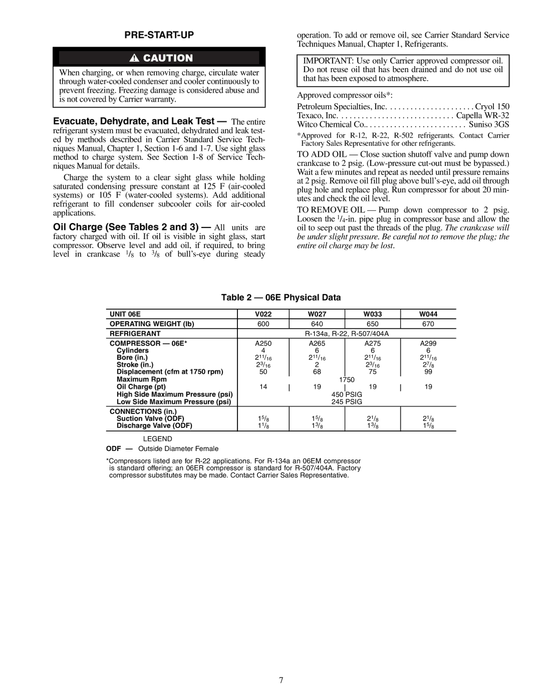
Oil Charge (See Tables 2 and 3) — All units are factory charged with oil. If oil is visible in sight glass, start compressor. Observe level and add oil, if required, to bring level in crankcase 1/8 to 3/8 of
operation. To add or remove oil, see Carrier Standard Service Techniques Manual, Chapter 1, Refrigerants.
IMPORTANT: Use only Carrier approved compressor oil. Do not reuse oil that has been drained and do not use oil that has been exposed to atmosphere.
Approved compressor oils*:
Petroleum Specialties, Inc. . . . . . . . . . . . . . . . . . . . . . Cryol 150 Texaco, Inc. . . . . . . . . . . . . . . . . . . . . . . . . . . . . Capella
*Approved for
TO ADD OIL — Close suction shutoff valve and pump down crankcase to 2 psig.
TO REMOVE OIL — Pump down compressor to 2 psig. Loosen the
Table 2 — 06E Physical Data
UNIT 06E | V022 |
| W027 |
|
| W033 |
| W044 |
OPERATING WEIGHT (lb) | 600 |
| 640 |
|
| 650 |
| 670 |
REFRIGERANT |
|
|
|
| ||||
COMPRESSOR — 06E* | A250 |
| A265 |
|
| A275 |
| A299 |
Cylinders | 4 |
| 6 |
|
| 6 |
| 6 |
Bore (in.) | 211/16 |
| 211/16 |
|
| 211/16 |
| 211/16 |
Stroke (in.) | 23/16 |
| 2 |
|
| 23/16 |
| 27/8 |
Displacement (cfm at 1750 rpm) | 50 |
| 68 |
|
| 75 |
| 99 |
Maximum Rpm |
|
|
| 1750 |
|
| ||
Oil Charge (pt) | 14 |
| 19 |
|
| 19 |
| 19 |
|
|
| ||||||
High Side Maximum Pressure (psi) |
|
|
| 450 |
| PSIG |
|
|
Low Side Maximum Pressure (psi) |
|
|
| 245 PSIG |
|
| ||
CONNECTIONS (in.) |
|
|
|
|
|
|
|
|
Suction Valve (ODF) | 15/8 |
| 15/8 |
|
| 21/8 |
| 21/8 |
Discharge Valve (ODF) | 11/8 |
| 13/8 |
|
| 13/8 |
| 15/8 |
LEGEND
ODF — Outside Diameter Female
*Compressors listed are for
7
