![]() CRANKSHAFT
CRANKSHAFT
CONNECTING ![]()
![]()
RODS AND
CAPS
OIL DRAIN PLUG (MAGNETIC)
BOTTOM
COVER
PLATE
OIL FILTER
SCREEN
Fig. 17 — View with Bottom Cover Plate Removed
CRANKSHAFT — Remove pump end bearing head and rotor. If connecting rod and piston assemblies are still in place. remove connecting rod caps and push piston assembly up into cylinder for crankshaft clearance. Pull crankshaft out through pump end opening. Inspect crankshaft journals for wear and tolerances shown in Table 7. Check oil passages and clean if clogged.
PUMP END MAIN BEARING — This bearing is a machined part of the oil pump and bearing head casting. Disassemble bearing head. If bearing is scored or worn, replace the complete bearing head.
CRANKCASE AND MOTOR END MAIN BEAR- INGS — These bearings are not field replaceable. If bearings are worn or damaged, replace compressor.
Table 7 — Wear Limits — 06E Compressor
|
| FACTORY TOL. | MAXIMUM | |
COMPRESSOR PART | (in.) | ALLOWABLE | ||
|
| Max | Min | WEAR* (in.) |
MOTOR END |
|
|
|
|
Main Bearing Diameter | 1.8760 | — | 0.001* | |
Journal Diameter |
| — | 1.8725 | |
|
| |||
PUMP END |
|
|
|
|
Main Bearing Diameter | 1.6260 | — | 0.001* | |
Journal Diameter |
| — | 1.6233 | |
|
| |||
CONNECTING ROD |
|
|
|
|
Bearing Diameter |
| 1.7515 | — |
|
(After Assembly) |
|
| 0.002* | |
Crankpin Diameter | — | 1.7483 |
| |
THRUSTWASHER |
| — | 0.155 | — |
(Thickness) |
| |||
|
|
|
| |
CYLINDERS |
|
|
|
|
Bore |
| 2.6885 | — | 0.002 |
Piston Diameter |
| — | 2.6817 | 0.002 |
Wrist Pin Diameter | — | 0.8748 | 0.001 | |
Con. Rod Wrist Pin ID | 0.8755 | — | 0.001 | |
Piston Ring End Gap | 0.007 | 0.002 | 0.015 | |
Piston Ring Side Clearance | 0.003 | 0.001 | 0.002 | |
VALVE | Suction | 0.0315 | 0.0305 | 0.002 |
THICKNESS |
|
|
| |
| 0.0255 | 0.0245 | ||
|
|
| ||
| Discharge | 0.0225 | 0.0215 | 0.002 |
END CLEARANCE |
| 0.031 | — | 0.010 |
*Maximum allowable wear above maximum or below minimum factory tolerances shown. For example: difference between main bearing diam- eter and journal diameter is .0035 in. (1.8760 – 1.8725) per factory tol- erances. Maximum allowable difference is .0045 in. (.0035 + .001).
Compressor Running Gear Replacement
CRANKSHAFT — Be sure compressor end bearing washer is in place on dowel pin. Install crankshaft through pump end, carefully guiding it through main bearings. Replace rotor.
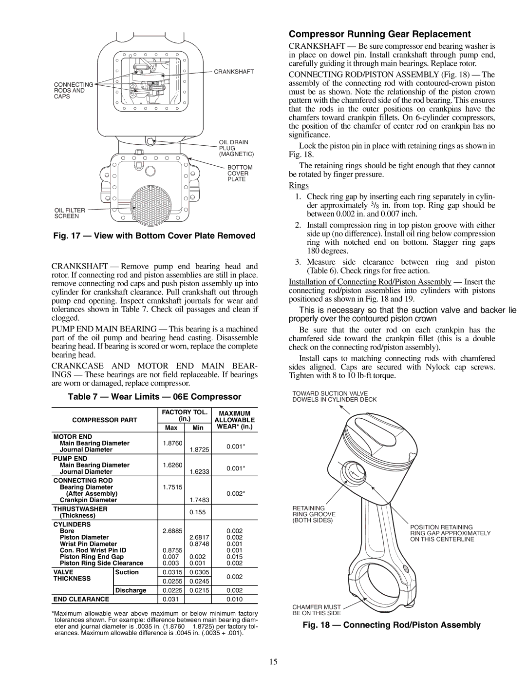
CONNECTING ROD/PISTON ASSEMBLY (Fig. 18) — The assembly of the connecting rod with
Lock the piston pin in place with retaining rings as shown in Fig. 18.
The retaining rings should be tight enough that they cannot be rotated by finger pressure.
Rings
1.Check ring gap by inserting each ring separately in cylin- der approximately 3/8 in. from top. Ring gap should be between 0.002 in. and 0.007 inch.
2.Install compression ring in top piston groove with either side up (no difference). Install oil ring below compression ring with notched end on bottom. Stagger ring gaps 180 degrees.
3.Measure side clearance between ring and piston (Table 6). Check rings for free action.
Installation of Connecting Rod/Piston Assembly — Insert the connecting rod/piston assemblies into cylinders with pistons positioned as shown in Fig. 18 and 19.
This is necessary so that the suction valve and backer lie properly over the contoured piston crown.
Be sure that the outer rod on each crankpin has the chamfered side toward the crankpin fillet (this is a double check on the connecting rod/piston assembly).
Install caps to matching connecting rods with chamfered sides aligned. Caps are secured with Nylock cap screws. Tighten with 8 to 10
TOWARD SUCTION VALVE
DOWELS IN CYLINDER DECK
RETAINING RING GROOVE (BOTH SIDES)
POSITION RETAINING
RING GAP APPROXIMATELY ON THIS CENTERLINE
CHAMFER MUST ![]()
BE ON THIS SIDE
Fig. 18 — Connecting Rod/Piston Assembly
15