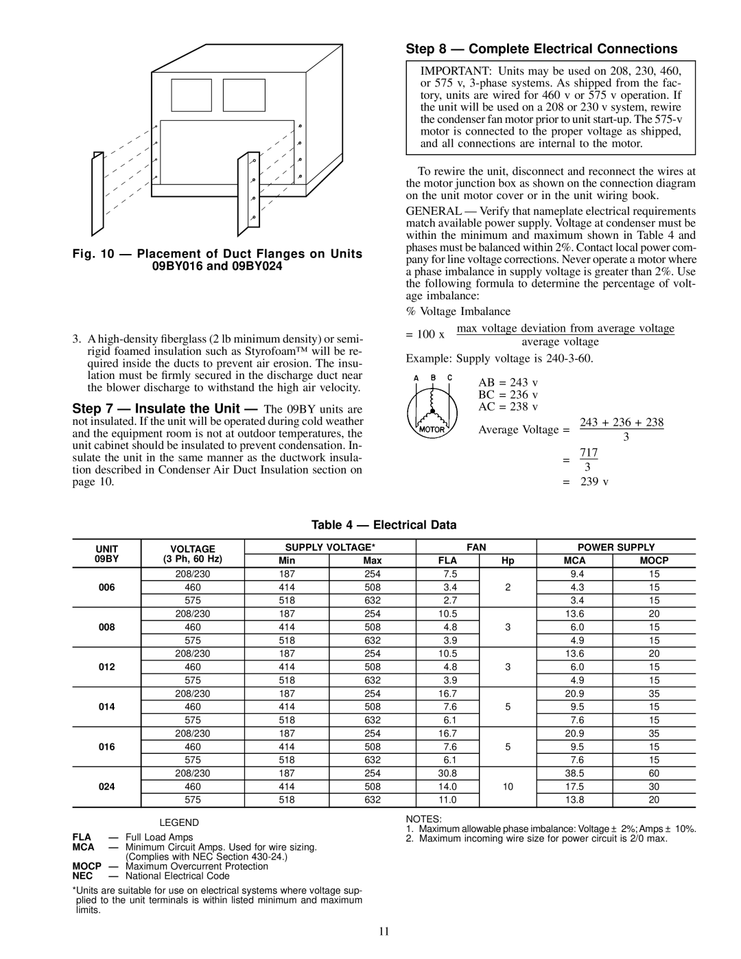
Fig. 10 Ð Placement of Duct Flanges on Units

09BY016 and 09BY024

3.A high-density ®berglass (2 lb minimum density) or semi- rigid foamed insulation such as Styrofoam™ will be re- quired inside the ducts to prevent air erosion. The insu- lation must be ®rmly secured in the discharge duct near the blower discharge to withstand the high air velocity.

Step 7 Ð Insulate the Unit Ð The 09BY units are not insulated. If the unit will be operated during cold weather and the equipment room is not at outdoor temperatures, the unit cabinet should be insulated to prevent condensation. In- sulate the unit in the same manner as the ductwork insula- tion described in Condenser Air Duct Insulation section on page 10.

Step 8 Ð Complete Electrical Connections

IMPORTANT: Units may be used on 208, 230, 460, or 575 v, 3-phase systems. As shipped from the fac- tory, units are wired for 460 v or 575 v operation. If the unit will be used on a 208 or 230 v system, rewire the condenser fan motor prior to unit start-up. The 575-v motor is connected to the proper voltage as shipped, and all connections are internal to the motor.

To rewire the unit, disconnect and reconnect the wires at the motor junction box as shown on the connection diagram on the unit motor cover or in the unit wiring book.

GENERAL Ð Verify that nameplate electrical requirements match available power supply. Voltage at condenser must be within the minimum and maximum shown in Table 4 and phases must be balanced within 2%. Contact local power com- pany for line voltage corrections. Never operate a motor where a phase imbalance in supply voltage is greater than 2%. Use the following formula to determine the percentage of volt- age imbalance:

% Voltage Imbalance

= 100 x

max voltage deviation from average voltage

average voltage


Example: Supply voltage is 240-3-60.

AB = 243 v

BC = 236 v

AC = 238 v

243 + 236 + 238

Average Voltage =

3

717

=

3

= 239 v

Table 4 Ð Electrical Data

UNIT

VOLTAGE

SUPPLY VOLTAGE*


FAN

POWER SUPPLY

09BY

(3 Ph, 60 Hz)

Min

Max

FLA


Hp

MCA

MOCP


208/230

187

254

7.5


9.4

15

006

460

414

508

3.4


2

4.3

15


575

518

632

2.7


3.4

15


208/230

187

254

10.5


13.6

20

008

460

414

508

4.8


3

6.0

15


575

518

632

3.9


4.9

15


208/230

187

254

10.5


13.6

20

012

460

414

508

4.8


3

6.0

15


575

518

632

3.9


4.9

15


208/230

187

254

16.7


20.9

35

014

460

414

508

7.6


5

9.5

15


575

518

632

6.1


7.6

15


208/230

187

254

16.7


20.9

35

016

460

414

508

7.6


5

9.5

15


575

518

632

6.1


7.6

15


208/230

187

254

30.8


38.5

60

024

460

414

508

14.0


10

17.5

30


575

518

632

11.0


13.8

20


LEGEND

FLA

Ð Full Load Amps

MCA

Ð Minimum Circuit Amps. Used for wire sizing.


(Complies with NEC Section 430-24.)

MOCP Ð Maximum Overcurrent Protection

NEC

Ð National Electrical Code

*Units are suitable for use on electrical systems where voltage sup- plied to the unit terminals is within listed minimum and maximum limits.

NOTES:

1.Maximum allowable phase imbalance: Voltage ± 2%; Amps ± 10%.

2.Maximum incoming wire size for power circuit is 2/0 max.

11

Page 11
Image 11
Carrier 09BY006-024 dimensions Electrical Data, Unit Voltage Supply Voltage FAN Power Supply, Fla Mca, Nec

09BY006-024 specifications

The Carrier 09BY006-024 is a high-efficiency air conditioning unit designed to provide reliable cooling solutions for both residential and commercial spaces. Known for its innovative technologies and superior performance, this model is specifically engineered to ensure optimal indoor comfort while minimizing energy consumption.

One of the standout features of the 09BY006-024 is its advanced inverter technology. This system allows the unit to adjust its cooling capacity according to the ambient temperature, resulting in significant energy savings. The inverter compressor operates at variable speeds, which not only reduces electricity bills but also enhances the overall lifespan of the unit by minimizing wear and tear.

The 09BY006-024 is equipped with an environmentally friendly refrigerant, R-410A, which is designed to have a minimal impact on the ozone layer and offers better thermal efficiency compared to traditional refrigerants. This makes it a suitable choice for environmentally conscious consumers looking to reduce their carbon footprint without compromising on cooling performance.

Furthermore, this model features a robust filtration system that includes a multi-stage filter designed to trap airborne pollutants, allergens, and dust particles. This ensures that the air circulated within the living or working space remains clean and healthy. The filters are easily accessible and can be cleaned or replaced, making maintenance hassle-free.

For user convenience, the Carrier 09BY006-024 comes with a user-friendly remote control and has options for smart home integration. This allows users to monitor and adjust settings from their smartphones or tablets, providing flexibility and control over their indoor climate.

In terms of design, the unit boasts a sleek and modern appearance, making it a stylish addition to any setting. Its compact size ensures that it can fit into various installation spaces without taking up valuable room.

Another key characteristic is its quiet operation. The Carrier 09BY006-024 is engineered with noise-reducing technologies that allow it to operate quietly, ensuring that it does not disrupt the peace in homes or workplaces.

In summary, the Carrier 09BY006-024 combines innovative technology, energy efficiency, and user-friendly features to deliver an exceptional cooling experience. Its commitment to environmental responsibility, combined with high-performance capabilities, makes it a top choice for anyone looking to enhance their indoor comfort.