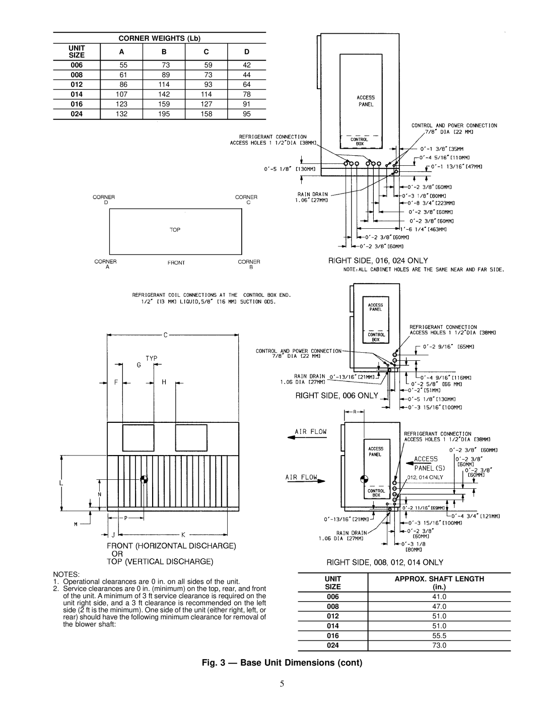
09BY006-024 specifications
The Carrier 09BY006-024 is a high-efficiency air conditioning unit designed to provide reliable cooling solutions for both residential and commercial spaces. Known for its innovative technologies and superior performance, this model is specifically engineered to ensure optimal indoor comfort while minimizing energy consumption.One of the standout features of the 09BY006-024 is its advanced inverter technology. This system allows the unit to adjust its cooling capacity according to the ambient temperature, resulting in significant energy savings. The inverter compressor operates at variable speeds, which not only reduces electricity bills but also enhances the overall lifespan of the unit by minimizing wear and tear.
The 09BY006-024 is equipped with an environmentally friendly refrigerant, R-410A, which is designed to have a minimal impact on the ozone layer and offers better thermal efficiency compared to traditional refrigerants. This makes it a suitable choice for environmentally conscious consumers looking to reduce their carbon footprint without compromising on cooling performance.
Furthermore, this model features a robust filtration system that includes a multi-stage filter designed to trap airborne pollutants, allergens, and dust particles. This ensures that the air circulated within the living or working space remains clean and healthy. The filters are easily accessible and can be cleaned or replaced, making maintenance hassle-free.
For user convenience, the Carrier 09BY006-024 comes with a user-friendly remote control and has options for smart home integration. This allows users to monitor and adjust settings from their smartphones or tablets, providing flexibility and control over their indoor climate.
In terms of design, the unit boasts a sleek and modern appearance, making it a stylish addition to any setting. Its compact size ensures that it can fit into various installation spaces without taking up valuable room.
Another key characteristic is its quiet operation. The Carrier 09BY006-024 is engineered with noise-reducing technologies that allow it to operate quietly, ensuring that it does not disrupt the peace in homes or workplaces.
In summary, the Carrier 09BY006-024 combines innovative technology, energy efficiency, and user-friendly features to deliver an exceptional cooling experience. Its commitment to environmental responsibility, combined with high-performance capabilities, makes it a top choice for anyone looking to enhance their indoor comfort.

