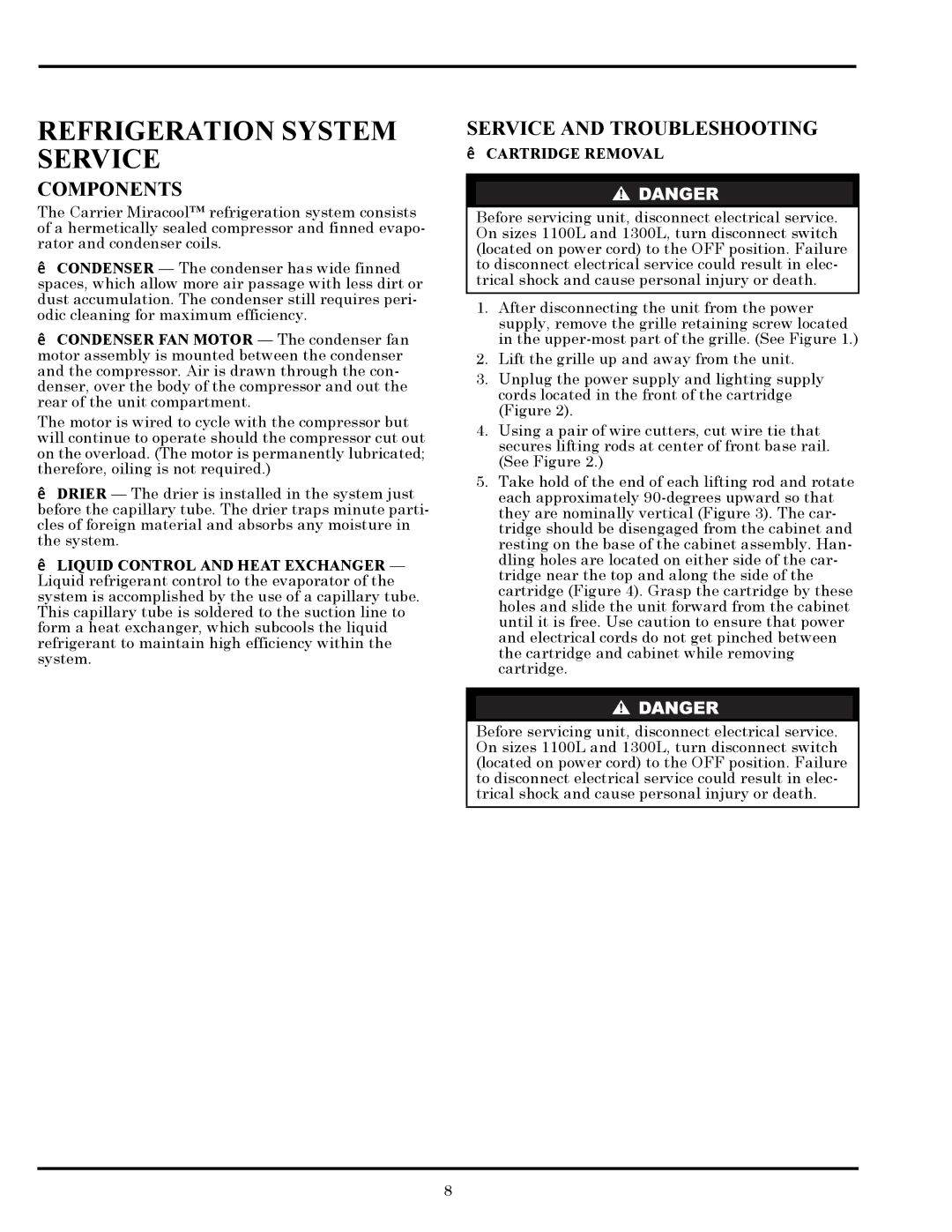
1300L, 260L specifications
The Carrier 260L and 1300L represent notable advancements in the realm of air conditioning systems, particularly designed for both commercial and industrial applications. These models are renowned for their efficiency, robust performance, and the integration of cutting-edge technologies.The Carrier 260L is characterized by its remarkable energy efficiency, with a focus on reducing operational costs while maintaining optimal cooling performance. It is available in various capacities, making it suitable for a wide range of spaces, from medium-sized commercial installations to large-scale industrial facilities. The model incorporates advanced inverter technology, enabling it to adjust the compressor speed according to the cooling demand. This results in both energy savings and enhanced comfort, as the system can maintain a stable temperature with minimal fluctuations.
In contrast, the Carrier 1300L is tailored for larger industrial applications, offering even greater cooling capacities. This model is designed to tackle high thermal loads, making it ideal for factories, warehouses, and other large spaces where cooling requirements can fluctuate significantly. The 1300L also features robust construction principles, ensuring reliability and longevity even in demanding environments.
Both models share several key features that elevate their performance. They are equipped with eco-friendly refrigerants, aligning with global sustainability efforts. The units boast sophisticated control systems that allow for precise temperature management, remote monitoring, and integration with building management systems. This not only enhances user convenience but also promotes energy management strategies that are increasingly critical in today's energy-conscious world.
Moreover, the Carrier 260L and 1300L are designed with ease of maintenance in mind. Their modular components facilitate quicker access for service technicians, ensuring minimal downtime. Enhanced filtration systems improve indoor air quality, capturing dust and other particulates effectively, which is a key consideration in commercial settings.
In summary, Carrier's 260L and 1300L models stand out for their energy efficiency, advanced technology integration, and user-friendly features. They effectively meet the cooling challenges faced in commercial and industrial environments while adhering to sustainability goals, enhancing both user experience and operational efficiency. These systems exemplify Carrier's commitment to quality, reliability, and innovation in air conditioning solutions.

