ALL FLOTRONIC UNITS - Units require control relays R) and Time Delay Module. They may be ob- tained ! rom your Carrier distributor under the following Carrier Part Numbers:


Rl and R2

115-v

HN61KK041

DPDT


23Cbv

HN61KK913

DPDT


R3

24-v

H N 6 1 K K 0 4 0

DPDT


Time Delay Module


30HK501602


UNITS 30HK,HL015 THROUGH 060 (Except 020, 60 Hz, and 0 15, 50 Hz.)

IMPORTANT: On 30HK,HL 2-compressor units, the SEQUENCE switch on the control panel must be in the l-2 position to obtain hot gas bypass operation.

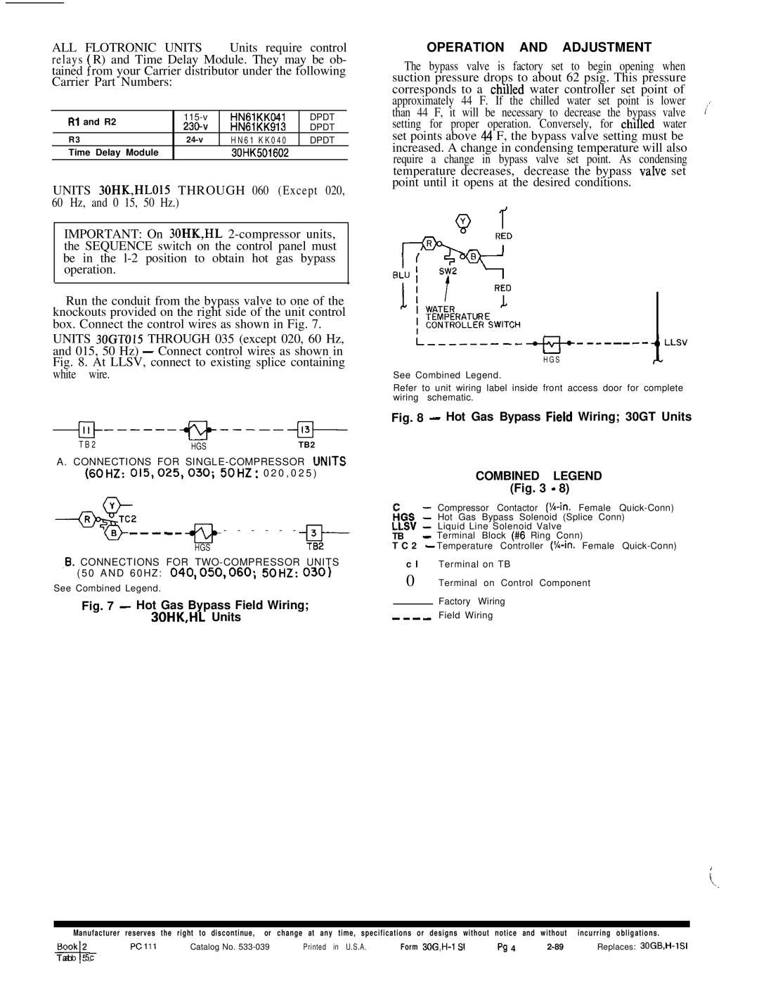
Run the conduit from the bypass valve to one of the knockouts provided on the right side of the unit control box. Connect the control wires as shown in Fig. 7.

UNITS 30GTO15 THROUGH 035 (except 020, 60 Hz, and 015, 50 Hz) - Connect control wires as shown in Fig. 8. At LLSV, connect to existing splice containing white wire.

-j+------+g+----+J-

T B 2HGSTB2

A . CONNECTIONS FOR SINGLE - COMPRESSOR UNITS (60~~: 015,025,030; 50~z: 0 2 0 , 0 2 5 )

-me--

- - - - - -

HGS

-El--

TB2

,B. CONNECTIONS FOR TWO - COMPRESSOR UNITS ( 5 0 A N D 6 0 H Z : 040,050,060; 50HZ: 0301

See Combined Legend.

Fig. 7 - Hot Gas Bypass Field Wiring;

30HK,HL Units

OPERATION AND ADJUSTMENT

The bypass valve is factory set to begin opening when suction pressure drops to about 62 psig. This pressure corresponds to a chllled water controller set point of approximately 44 F. If the chilled water set point is lower than 44 F, it will be necessary to decrease the bypass valve y; setting for proper operation. Conversely, for chllled water set points above 44 F, the bypass valve setting must be increased. A change in condensing temperature will also require a change in bypass valve set point. As condensing temperature decreases, decrease the bypass vaIve set point until it opens at the desired conditions.

i,--------

--e---t-

LLSV

H G S


i

See Combined Legend.

Refer to unit wiring label inside front access door for complete wiring schematic.

Fig. 8 - Hot Gas Bypass Fierd Wiring; 30GT Units

COMBINED LEGEND (Fig. 3 - 8)

Compressor Contactor (%-in. Female Quick-Conn) FiGS 1 Hot Gas Bypass Solenoid (Splice Conn)

LLSV - Liquid Line Solenoid Valve

TB - Terminal Block (#6 Ring Conn)

T C 2 - Temperature Controller (X-in. Female Quick-Conn)

c l Terminal on TB

0 Terminal on Control Component

Factory Wiring

----Field Wiring

Manufacturer reserves the right to discontinue, or change at any time, specifications or designs without notice and without incurring obligations.

Book 2

PC171

Catalog No. 533-039

Printed in U.S.A.

Form 30G,H-1 S1

PC4 4

2-89

Replaces: 30GB,WlSI

-T a+b 5c

Page 4
Image 4
Carrier 30GT specifications +------+g+----+J, Operation and Adjustment

30GT specifications

The Carrier 30GT is a high-efficiency, air-cooled chiller designed to provide reliable cooling solutions for commercial and industrial applications. Known for its innovative technologies and advanced features, the 30GT stands out in the HVAC market for its efficiency and ease of operation.

One of the defining characteristics of the Carrier 30GT is its compact design, which allows for easy installation and integration into existing systems, making it suitable for various building types. The chiller is equipped with a robust scroll compressor that ensures a considerable reduction in energy consumption compared to conventional chillers. With its high-efficiency compressors, the 30GT achieves superior performance ratings, contributing to reduced operational costs over its lifespan.

The unit incorporates advanced microprocessor control technology, which enables precise monitoring and adjustment of operating parameters. This smart control system enhances the performance of the chiller, optimally regulating temperature and energy use to meet fluctuating demand. Additionally, the intuitive user interface provides real-time data and diagnostics, facilitating simplified maintenance and operational oversight.

In terms of environmental responsibility, the Carrier 30GT is designed to comply with the latest regulations regarding refrigerants. It utilizes non-ozone-depleting refrigerants, contributing to environmentally friendly operations. Moreover, the chiller is fitted with advanced sound-dampening technology, ensuring quiet operation, which is particularly beneficial for installations in noise-sensitive environments.

The Carrier 30GT also features flexible configuration options, allowing for tailored solutions to meet specific application requirements. It can be easily connected to building management systems (BMS) to enhance energy management and operational efficiency.

Durability is another hallmark of the 30GT. Constructed with high-quality materials, it is designed to withstand harsh weather conditions and demanding operational environments. This resilience ensures that the chiller maintains optimal performance and longevity, enhancing its return on investment.

Overall, the Carrier 30GT combines efficiency, innovation, and reliability, making it an ideal choice for those seeking advanced cooling solutions in commercial and industrial applications. With its range of features and technologies, the 30GT sets a standard in the HVAC industry, providing a reliable and sustainable option for temperature control.