Carrier 320720---751 THRU ---761 Installation, Kit Usage, Remove Whole Cell Panel Assembly

Models: 320720---751 THRU ---761

1 6
Download 6 pages 55.18 Kb
Page 2
Image 2
320720

320720

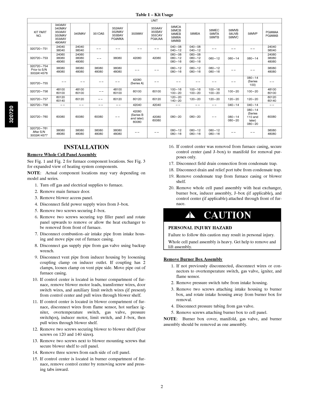
Table 1 – Kit Usage

UNIT


340AAV


352AAV


355AAV

58MCA


340MAV


58MEC

58MVB


58MCB


KIT PART

350AAV

345MAV

351DAS

352MAV

355MAV

355BAV

58MSA

58MVP

PG9MAA

58MEB

58MTA

58UVB

NO.


350MAV

353BAV

355CAV

PG9MAB


58MXA


58MTB

58MVC


353AAV


PG9MXA


PG9UAA


58MXB


490AAV


320720---

751

24040

24040


--- ---

--- ---

--- ---

040

--- 08

040

--- 08

--- ---

--- ---

--- ---

24040

36040

36040

--- ---

040

--- 12

040

--- 12

36040


24060

24060


060

--- 08

060

--- 08


24060

320720---

753

36060

36060

--- ---

36060

42060

42060

060

--- 12

060

--- 12

060---

12

060---

14

060---

14

36060


48060

48060


060

--- 16

060

--- 16


48060


320720---

754

36080

36080

36080

36080


080

--- 12

080

--- 12

080

12


36080

Prior to S/N


--- ---

--- ---

--- ---

48080

48080

48080

48080

--- ---

080

--- 16

080

--- 16

080

16

48080

3002A14578


42080


080---

14


--- ---

--- ---

--- ---

--- ---


--- ---


--- ---

--- ---

--- ---

(Series


320720---

755

--- ---

(Series A)


--- ---


100)


320720---

756

48100

48100


48100

60100

60100

100

--- 16

100

--- 16

100---

16

100

20

100

20

48100

60100

60100

--- ---

60100

100

--- 20

100

--- 20

100

20

60100


320720---

757

60120

60120


60120

60120

60120

120

--- 20

120

--- 20

120

20

120

20

120

20

60120

60140

--- ---

140

--- 20

60140


320720---

758

--- ---

--- ---

--- ---

--- ---

42040

42040


--- ---


--- ---

--- ---

040---

14

040---

14

--- ---


42080


080---

14


(Series


320720---

760

60080

60080

60080


(Series B

42080

080

--- 20

080

--- 20


080

14

60080


110 and

--- ---

and later)

--- ---


60080


080

20

later)


60080


080

20


320720---

761

36080

36080

36080

36080


080

--- 12

080

--- 12

080

12


36080

After S/N


--- ---

--- ---

--- ---

48080

48080

48080

48080

--- ---

080

--- 16

080

--- 16

080

16

48080

3002A14577


INSTALLATION

Remove Whole Cell Panel Assembly

See Fig. 1 and Fig. 2 for furnace component locations. See Fig. 3 for expanded view of heating system components.

NOTE: Actual component locations may vary depending on model and series.

1.Turn off gas and electrical supplies to furnace.

2.Remove main furnace door.

3.Remove blower access panel.

4.Disconnect field power supply wires from J-box.

5.Remove two screws securing J-box.

6.Remove two screws securing top filler panel and rotate panel upwards to remove or allow the heat exchanger to be removed from front of furnace.

7.Disconnect combustion-air intake pipe from intake hous- ing and move pipe out of furnace casing.

8.Disconnect gas supply pipe from gas valve using backup wrench.

9.Disconnect vent pipe from inducer housing by loosening coupling clamp on inducer outlet. If coupling has 2 clamps, loosen clamp on vent pipe side. Move pipe out of furnace casing.

10.If control center is located in burner compartment of fur- nace, remove blower motor leads, transformer wires, door switch wires, and auxiliary limit switch wires (if present) from control center and pull wires through blower shelf.

11.If control center is located in blower compartment of fur- nace, disconnect wires from flame sensor, hot surface ig- niter, overtemperature switch, gas valve, pressure switch(es), inducer motor, limit switch, and J-box, then pull wires through blower shelf.

12.Remove two screws securing blower to blower shelf (four screws on 120 and 140 sizes).

13.Remove two screws next to blower mounting screws that secure blower shelf to cell panel.

14.Remove three screws from each side of cell panel.

15.If control center is located in burner compartment of fur- nace, remove control center by removing screw and press- ing tabs inward.

16.If control center was removed from furnace casing, secure control center (and J-box) to manifold for removal pur- poses only.

17.Disconnect field drain connection from condensate trap.

18.Disconnect drain and relief port tube from condensate trap.

19.Remove condensate trap from furnace casing or blower shelf.

20.Remove whole cell panel assembly with heat exchanger, burner box, inducer assembly, J-box (if applicable), and control center (if applicable) attached through front of fur- nace.

!CAUTION

PERSONAL INJURY HAZARD

Failure to follow this caution may result in personal injury.

Whole cell panel assembly is heavy. Get help to remove and lift assembly.

Remove Burner Box Assembly

1.If not previously disconnected, disconnect wires or con- nectors to overtemperature switch, gas valve, igniter, and flame sensor.

2.Remove pressure switch tube from intake housing.

3.Remove two screws attaching intake housing to burner box, and rotate intake housing away from burner box for removal.

4.Disconnect pressure tubing from gas valve.

5.Remove screws attaching burner box to cell panel.

NOTE: Burner box cover, manifold, gas valve, and burner assembly should be removed as one assembly.

2

Page 2
Image 2
Carrier 320720---751 THRU ---761 Installation, Kit Usage, Remove Whole Cell Panel Assembly, Personal Injury Hazard