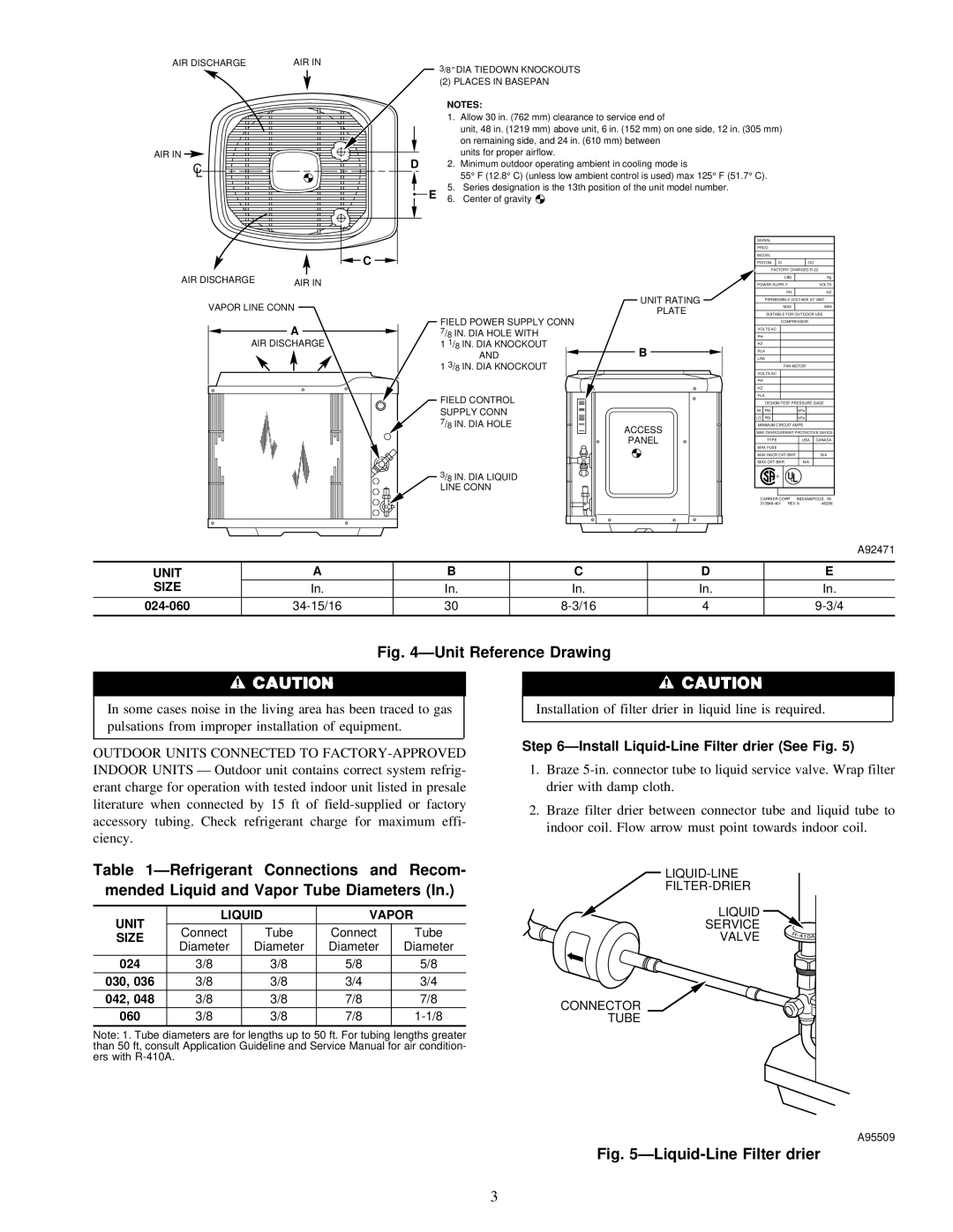
38TXA specifications
The Carrier 38TXA is a premium air conditioning solution designed for residential and light commercial applications, offering reliable performance and energy efficiency. As a standout model in Carrier's extensive lineup, the 38TXA is equipped with advanced features and technologies that ensure optimal comfort throughout the year.At the heart of the 38TXA is its variable-speed compressor, which allows for precise temperature control and superior humidity regulation. This technology enables the unit to operate at different speeds, adjusting to the cooling demands of the space. Consequently, users benefit from improved energy efficiency, with SEER ratings often exceeding 16, contributing to reduced energy bills.
The 38TXA comes with a robust, weather-resistant cabinet that protects its internal components from the elements, enhancing durability and extending the lifespan of the unit. Additionally, it features a quiet operation mode; its sound levels are engineered to minimize noise, ensuring a peaceful indoor environment.
Another remarkable attribute of the Carrier 38TXA is its compatibility with smart home systems, allowing homeowners to integrate temperature control with other smart technologies. This connectivity is facilitated by the Carrier Comfort™ app, which provides users with the ability to adjust settings remotely, monitor energy usage, and optimize performance.
In terms of installation flexibility, the 38TXA can be easily integrated into existing HVAC systems or serve as a standalone unit. This versatility is complemented by its wide range of available sizes, catering to various space requirements.
The unit also utilizes environmentally friendly refrigerants, aligning with modern standards for sustainability. This commitment to eco-friendly practices not only meets regulatory requirements but also offers peace of mind to environmentally conscious consumers.
Overall, the Carrier 38TXA is designed with cutting-edge technologies aimed at maximizing efficiency, comfort, and convenience. Its combination of advanced features, robust design, and user-friendly connectivity make it an ideal choice for those seeking reliable climate control in their homes or businesses. With the 38TXA, Carrier continues its legacy of innovation, ensuring that customers enjoy enhanced comfort while minimizing their environmental footprint.

