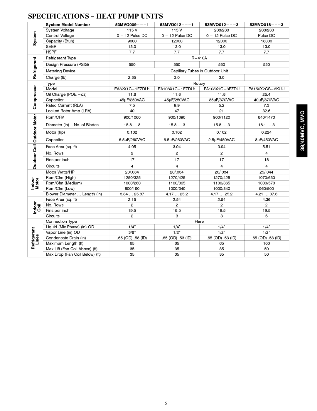
40MVQ, 40MVC, 38MVQ, 38MVC specifications
The Carrier 38MVC, 38MVQ, 40MVC, and 40MVQ are advanced air-conditioning systems designed for both residential and commercial applications. These units are recognizable for their commitment to efficiency, reliability, and comfort, making them ideal choices for various environments.One of the standout features of these models is their high energy efficiency ratings. Both the 38MVC and 38MVQ boast Seasonal Energy Efficiency Ratios (SEER) that exceed industry standards, delivering substantial energy savings over time. The 40MVC and 40MVQ models also continue this trend, featuring enhanced efficiency that translates into lower utility bills and a reduced carbon footprint.
These air-conditioning units utilize Carrier's innovative inverter technology, which allows for variable speed operation. This means that the compressor can adjust its speed according to the cooling demand, resulting in smoother temperature control and less energy consumption. The inverter technology not only maximizes comfort but also contributes to quieter operation, as the systems can run at lower speeds when full capacity is not required.
In addition to efficiency, the Carrier 38MVC, 38MVQ, 40MVC, and 40MVQ are equipped with advanced filtration systems. These systems work to purify the air by reducing allergens and pollutants, ensuring a healthier indoor environment. Some models also come equipped with smart connectivity options, allowing users to control their air conditioning remotely via a smartphone app. This feature adds convenience and helps monitor energy usage effectively.
With durable construction and high-quality components, these units are designed to withstand the test of time, reducing the need for frequent repairs or replacements. They are also built to operate quietly, so they can provide comfort without disturbing the peace of the indoor environment.
In terms of installation flexibility, the Carrier 38MVC, 38MVQ, 40MVC, and 40MVQ can be easily integrated into various existing HVAC systems, thanks to their compatible size and design. This adaptability makes them suitable for a wide range of applications, from small residential homes to larger commercial spaces.
Overall, the Carrier 38MVC, 38MVQ, 40MVC, and 40MVQ models are engineered with cutting-edge technologies that prioritize efficiency, comfort, and ease of use, making them an excellent choice for those looking to enhance their indoor climate control solutions.
