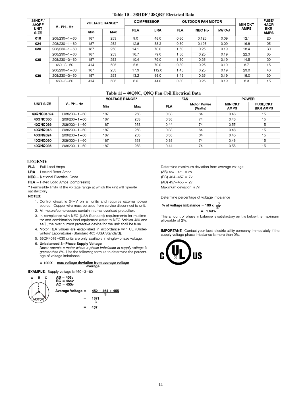
Table 10 – 38HDF / 38QRF Electrical Data

38HDF /


VOLTAGE RANGE*

COMPRESSOR

OUTDOOR FAN MOTOR

MIN CKT

FUSE/

38QRF

V---PH ---

Hz


HACR

UNIT


RLA

LRA

FLA

NEC Hp

kW Out

AMPS

BKR

SIZE


Min

Max


AMPS


018

208/230---

1---

60

187

253

9.0

48.0

0.80

0.125

0.09

12.1

20


024

208/230---

1---

60

187

253

12.8

58.3

0.80

0.125

0.09

16.8

25


030

208/230---

1---

60

187

253

14.1

73.0

1.50

0.25

0.19

18.4

30


208/230---

1---

60

187

253

16.7

79.0

1.50

0.25

0.19

22.3

35

035


208/230---

3---

60

187

253

10.4

79.0

1.50

0.25

0.19

14.5

20


460---

3---

60

414

506

5.8

79.0

0.80

0.25

0.19

8.7

15


208/230---

1---

60

187

253

17.9

112.0

1.45

0.25

0.19

23.8

40

036


208/230---

3---

60

187

253

13.2

88.0

1.45

0.25

0.19

18.0

30


460---

3---

60

414

506

6.0

44.0

0.80

0.25

0.19

8.3

15


Table 11 – 40QNC, QNQ Fan Coil Electrical Data


VOLTAGE RANGE*


FAN


POWER

UNIT SIZE

V PH

Hz


Min

Max

FLA


Motor Power

MIN CKT


FUSE/CKT


(Watts)

AMPS


BKR AMPS


40QNC01824

208/230---

1---

60

187

253

0.38


64

0.48


15


40QNC030

208/230---

1---

60

187

253

0.38


74

0.48


15


40QNC036

208/230---

1---

60

187

253

0.44


74

0.55


15


40QNQ018

208/230---

1---

60

187

253

0.38


64

0.48


15


40QNQ024

208/230---

1---

60

187

253

0.38


64

0.48


15


40QNQ030

208/230---

1---

60

187

253

0.38


74

0.48


15


40QNQ036

208/230---

1---

60

187

253

0.44


74

0.55


15

LEGEND:

FLA --- Full Load Amps

LRA --- Locked Rotor Amps

NEC --- National Electrical Code

RLA --- Rated Load Amps (compressor)

*Permissible limits of the voltage range at which the unit will operate satisfactorily

NOTES:

1.Control circuit is 24---V on all units and requires external power source. Copper wire must be used from service disconnect to unit.

2.All motors/compressors contain internal overload protection.

3.In compliance with NEC (USA Standard) requirements for multimo- tor and combination load equipment (refer to NEC Articles 430 and 440), the over current protective device for the unit shall be fuse.

4.Motor RLA values are established in accordance with UL (Under- writers’ Laboratories) Standard 465 (USA Standard).

5.38QRF018---030 units are only available in single ---phase voltage.

6.Unbalanced 3---Phase Supply Voltage

Never operate a motor where a phase imbalance in supply voltage is greater than 2%. Use the following formula to determine the percent- age of voltage imbalance:

=100 X max voltage deviation from average voltage average

EXAMPLE: Supply voltage is 460---3---60

AB = 452v

BC = 464v

AC = 455v

Average Voltage = 452 + 464 + 455 3

=1371

3

=457

Determine maximum deviation from average voltage:

(AB) 457---

452 = 5v

(BC) 464---

457 = 7v

(AC) 457---

455 = 2v

Maximum deviation is 7v.

Determine percentage of voltage imbalance

% of voltage imbalance = 100 x 7 57

= 1.53%

This amount of phase imbalance is satisfactory as it is below the maximum allowable of 2%.

IMPORTANT: Contact your local electric utility company immediately if the supply voltage phase imbalance is more than 2%.

11

Page 11
Image 11
Carrier 40QNQ installation instructions 38HDF / 38QRF Electrical Data, 40QNC, QNQ Fan Coil Electrical Data

40QNQ, 40QNC specifications

The Carrier 40QNC and 40QNQ are advanced rooftop packaged units designed for efficient heating and cooling in commercial applications. These units are particularly known for their reliability, versatility, and energy-efficient performance, making them a preferred choice for building owners and HVAC professionals alike.

One of the standout features of the Carrier 40QNC and 40QNQ units is their variable-speed technology. This innovative system allows for precise control of airflow and temperature, ensuring that indoor environments maintain consistent comfort levels while minimizing energy consumption. The variable-speed compressor operates at different speeds based on the cooling demand, leading to reduced energy costs and improved overall efficiency.

In terms of energy performance, both models boast high Seasonal Energy Efficiency Ratios (SEER) and Heating Seasonal Performance Factors (HSPF). This not only contributes to lower energy bills but also helps in meeting energy efficiency standards and regulations in various regions. This makes the 40QNC and 40QNQ ideal for environmentally conscious building projects aiming for sustainability.

Another notable feature is the advanced microchannel coil technology utilized in these units. Microchannel coils are lighter, more compact, and provide enhanced heat exchange capabilities compared to traditional coils. This technology contributes to a more efficient refrigerant flow and ultimately leads to improved performance and durability of the unit.

Moreover, both models come equipped with a robust control system that enhances user interface. With smart thermostat compatibility, users can easily manage their building's climate remotely, ensuring optimal comfort and energy management. These systems are designed to integrate seamlessly with building management systems (BMS), allowing for greater control and optimization.

The construction of the Carrier 40QNC and 40QNQ also deserves mention. The units are built with durable materials designed to withstand harsh weather conditions, providing longevity and reliability. Additionally, the low sound levels produced by these units make them suitable for noise-sensitive settings, ensuring comfort without disruptive operation.

In summary, the Carrier 40QNC and 40QNQ are exemplary rooftop packaged units that combine advanced technology, energy efficiency, and reliable performance. Their variable-speed operation, microchannel coil technology, and robust control systems make them ideal solutions for commercial heating and cooling needs, catering to both comfort and sustainability.