38QRF Units

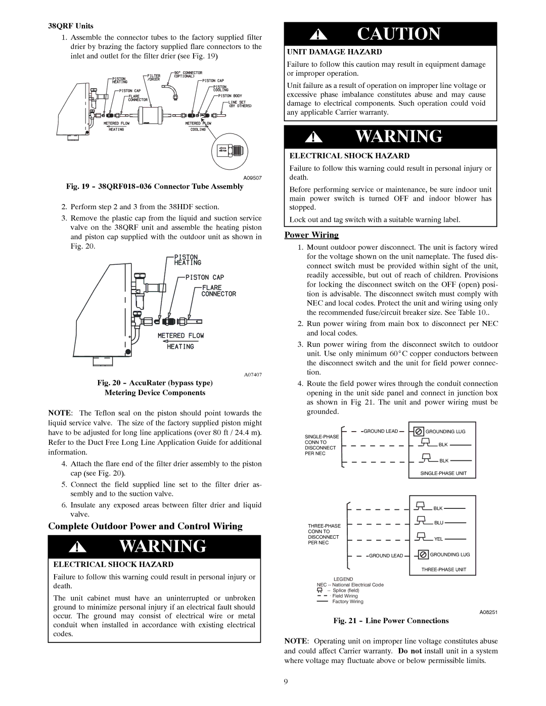
1.Assemble the connector tubes to the factory supplied filter drier by brazing the factory supplied flare connectors to the inlet and outlet for the filter drier (see Fig. 19)

A09507

Fig. 19 - 38QRF018-036 Connector Tube Assembly

2.Perform step 2 and 3 from the 38HDF section.

3.Remove the plastic cap from the liquid and suction service valve on the 38QRF unit and assemble the heating piston and piston cap supplied with the outdoor unit as shown in Fig. 20.

A07407

Fig. 20 - AccuRater (bypass type)

Metering Device Components

NOTE: The Teflon seal on the piston should point towards the liquid service valve. The size of the factory supplied piston might have to be adjusted for long line applications (over 80 ft / 24.4 m). Refer to the Duct Free Long Line Application Guide for additional information.

4.Attach the flare end of the filter drier assembly to the piston cap (see Fig. 20).

5.Connect the field supplied line set to the filter drier as- sembly and to the suction valve.

6.Insulate any exposed areas between filter drier and liquid valve.

Complete Outdoor Power and Control Wiring

!WARNING

ELECTRICAL SHOCK HAZARD

Failure to follow this warning could result in personal injury or death.

The unit cabinet must have an uninterrupted or unbroken ground to minimize personal injury if an electrical fault should occur. The ground may consist of electrical wire or metal conduit when installed in accordance with existing electrical codes.

!CAUTION

UNIT DAMAGE HAZARD

Failure to follow this caution may result in equipment damage or improper operation.

Unit failure as a result of operation on improper line voltage or excessive phase imbalance constitutes abuse and may cause damage to electrical components. Such operation could void any applicable Carrier warranty.

!WARNING

ELECTRICAL SHOCK HAZARD

Failure to follow this warning could result in personal injury or death.

Before performing service or maintenance, be sure indoor unit main power switch is turned OFF and indoor blower has stopped.

Lock out and tag switch with a suitable warning label.

Power Wiring

1.Mount outdoor power disconnect. The unit is factory wired for the voltage shown on the unit nameplate. The fused dis- connect switch must be provided within sight of the unit, readily accessible, but out of reach of children. Provisions for locking the disconnect switch on the OFF (open) posi- tion is advisable. The disconnect switch must comply with NEC and local codes. Protect the unit and wiring using only the recommended fuse/circuit breaker size. See Table 10..

2.Run power wiring from main box to disconnect per NEC and local codes.

3.Run power wiring from the disconnect switch to outdoor unit. Use only minimum 60_C copper conductors between the disconnect switch and the unit for field power connec- tion.

4.Route the field power wires through the conduit connection opening in the unit side panel and connect in junction box as shown in Fig 21. The unit and power wiring must be grounded.

GROUND LEAD

GROUNDING LUG

SINGLE-PHASE


CONN TO

BLK

DISCONNECT


PER NEC


BLK


SINGLE-PHASE UNIT


BLK

THREE-PHASE

BLU


CONN TO


DISCONNECT

YEL

PER NEC


GROUND LEAD

GROUNDING LUG


THREE-PHASE UNIT

LEGEND


NEC -- National Electrical Code


-- Splice (field)


Field Wiring


Factory Wiring


A08251

Fig. 21 - Line Power Connections

NOTE: Operating unit on improper line voltage constitutes abuse and could affect Carrier warranty. Do not install unit in a system where voltage may fluctuate above or below permissible limits.

9

Page 9
Image 9
Carrier 40QNC, 40QNQ installation instructions Complete Outdoor Power and Control Wiring, Power Wiring, 38QRF Units

40QNQ, 40QNC specifications

The Carrier 40QNC and 40QNQ are advanced rooftop packaged units designed for efficient heating and cooling in commercial applications. These units are particularly known for their reliability, versatility, and energy-efficient performance, making them a preferred choice for building owners and HVAC professionals alike.

One of the standout features of the Carrier 40QNC and 40QNQ units is their variable-speed technology. This innovative system allows for precise control of airflow and temperature, ensuring that indoor environments maintain consistent comfort levels while minimizing energy consumption. The variable-speed compressor operates at different speeds based on the cooling demand, leading to reduced energy costs and improved overall efficiency.

In terms of energy performance, both models boast high Seasonal Energy Efficiency Ratios (SEER) and Heating Seasonal Performance Factors (HSPF). This not only contributes to lower energy bills but also helps in meeting energy efficiency standards and regulations in various regions. This makes the 40QNC and 40QNQ ideal for environmentally conscious building projects aiming for sustainability.

Another notable feature is the advanced microchannel coil technology utilized in these units. Microchannel coils are lighter, more compact, and provide enhanced heat exchange capabilities compared to traditional coils. This technology contributes to a more efficient refrigerant flow and ultimately leads to improved performance and durability of the unit.

Moreover, both models come equipped with a robust control system that enhances user interface. With smart thermostat compatibility, users can easily manage their building's climate remotely, ensuring optimal comfort and energy management. These systems are designed to integrate seamlessly with building management systems (BMS), allowing for greater control and optimization.

The construction of the Carrier 40QNC and 40QNQ also deserves mention. The units are built with durable materials designed to withstand harsh weather conditions, providing longevity and reliability. Additionally, the low sound levels produced by these units make them suitable for noise-sensitive settings, ensuring comfort without disruptive operation.

In summary, the Carrier 40QNC and 40QNQ are exemplary rooftop packaged units that combine advanced technology, energy efficiency, and reliable performance. Their variable-speed operation, microchannel coil technology, and robust control systems make them ideal solutions for commercial heating and cooling needs, catering to both comfort and sustainability.