The smoke detector contains a photoelectric detector approved for an extended air speed range of 100 to 4000 feet per minute and an operational temperature range of -4_to 158_F. Do not operate the smoke detector out of these ranges.

The smoke detector operates on 24 vac, 120 vac, or 220/240 vac. The thermostat power terminals on the unit are used to power the smoke detector.

The cover of the controller contains the Alarm, Trouble, Dirty and Power LEDs. The cover of the sensor contains the Alarm, Trouble and Power LEDs. (See Fig 2.)

The smoke detector can be reset by a momentary power interruption, by the reset button on the front cover, by the control panel, or by the remote reset accessory.

RETURN SENSOR

CONTROL MODULE

J1

J1

S

J2

E

RETURN SENSOR

CONTROL MODULE

J1

J1

S

J2

E


SECURE FROM BEHIND


WITH SCREW


TERMINAL STRIP

C07182

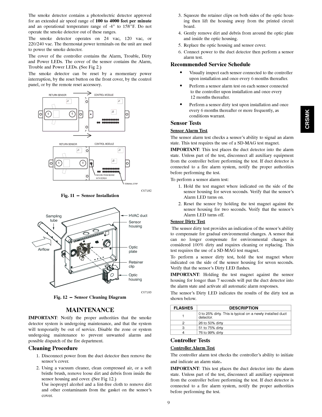
Fig. 11 ---Sensor Installation

3.Squeeze the retainer clips on both sides of the optic hous- ing then lift the housing away from the printed circuit board.

4.Gently remove dirt and debris from around the optic plate and inside the optic housing.

5.Replace the optic housing and sensor cover.

6.Connect power to the duct detector then perform a sensor alarm test.

Recommended Service Schedule

SVisually inspect each sensor connected to the controller upon installation and once every 6 months thereafter.

SPerform a sensor alarm test on each sensor connected to the controller upon installation and once every 12 months thereafter.

SPerform a sensor dirty test upon installation and once every 6 months thereafter or more frequently, as conditions warrant.

Sensor Tests

Sensor Alarm Test

The sensor alarm test checks a sensor’s ability to signal an alarm state. This test requires the use of a SD-MAG test magnet.

IMPORTANT: This test places the duct detector into the alarm state. Unless part of the test, disconnect all auxiliary equipment from the controller before performing the test. If duct detector is connected to a fire alarm system, notify the proper authorities before performing the test.

To perform a sensor alarm test:

1.

Hold the test magnet where indicated on the side of the


sensor housing for seven seconds. Verify that the sensor’s


Alarm LED turns on.

2.

Reset the sensor by holding the test magnet against the


sensor housing for two seconds. Verify that the sensor’s

CRSMK

Sampling

tube

Airflow

HVAC duct

Sensor housing

Optic plate

Retainer

clip

Optic housing

Alarm LED turns off.

Sensor Dirty Test

The sensor dirty test provides an indication of the sensor’s ability to compensate for gradual environmental changes. A sensor that can no longer compensate for environmental changes is considered 100% dirty and requires cleaning or replacing. This test requires the use of a SD-MAG test magnet.

To perform a sensor dirty test, hold the test magnet where indicated on the side of the sensor housing for seven seconds. Verify that the sensor’s Dirty LED flashes.

IMPORTANT: Holding the test magnet against the sensor housing for longer than 7 seconds will put the duct detector into the alarm state and activate all automatic alarm responses.

C07183

Fig. 12 ---Sensor Cleaning Diagram

MAINTENANCE

IMPORTANT: Notify the proper authorities that the smoke detector system is undergoing maintenance, and that the system will temporarily be out of service. Disable the zone or system undergoing maintenance to prevent unwanted alarms and possible dispatch of the fire department.

Cleaning Procedure

1.Disconnect power from the duct detector then remove the sensor’s cover.

2.Using a vacuum cleaner, clean compressed air, or a soft bristle brush, remove loose dirt and debris from inside the sensor housing and cover. (See Fig 12.)

Use isopropyl alcohol and a lint-free cloth to remove dirt and other contaminants from the gasket on the sensor’s cover.

The sensor’s Dirty LED indicates the results of the dirty test as shown below.

FLASHES

DESCRIPTION

10 to 25% dirty. This is typical on a newly installed duct detector.

226 to 50% dirty

351 to 75% dirty

476 to 99% dirty

Controller Tests

Controller Alarm Test

The controller alarm test checks the controller’s ability to initiate and indicate an alarm state.

IMPORTANT: This test places the duct detector into the alarm state. Unless part of the test, disconnect all auxiliary equipment from the controller before performing the test. If duct detector is connected to a fire alarm system, notify the proper authorities before performing the test.

9

Page 9
Image 9
Carrier 48/50HG014-028 Maintenance, Recommended Service Schedule, Sensor Tests, Cleaning Procedure, Controller Tests

48/50PG20-28, 48/50HG014-028 specifications

The Carrier 48/50HG014-028 and 48/50PG20-28 are part of Carrier's extensive lineup of commercial and industrial HVAC systems, designed for optimal performance, energy efficiency, and reliability. These units are particularly known for their robust construction and advanced technology, making them suitable for a variety of applications, including large commercial buildings, manufacturing centers, and other facilities that require consistent climate control.

One of the key features of the Carrier 48/50HG units is their high-efficiency scroll compressors, which not only enhance performance but also significantly reduce energy consumption. These compressors are designed to maintain efficiency across a wide range of operating conditions, providing reliable cooling and heating year-round. Additionally, the units are equipped with advanced microprocessor controls that allow for precise temperature regulation and system diagnostics, optimizing energy use and simplifying maintenance.

The 48/50HG and 48/50PG models also boast a compact design, making installation easier, especially in spaces with limited access. Their lightweight construction and modular components enable quick and efficient service, an essential feature for businesses that cannot afford prolonged downtimes. The units come with a comprehensive range of factory-installed options, including variable-speed fans and advanced economizer systems that increase indoor air quality while reducing operational costs.

Noise reduction technology is another significant characteristic of these units. They are designed with sound-dampening features that minimize operational noise, which is particularly beneficial for urban environments or noise-sensitive applications. In addition, the units meet or exceed standard regulatory requirements for efficiency and emissions, further enhancing their appeal in an increasingly eco-conscious market.

Moreover, the Carrier 48/50HG and 48/50PG series incorporate environmentally friendly refrigerants with low Global Warming Potential (GWP), aligning with Carrier's commitment to sustainability. This approach not only complies with current environmental regulations but also prepares users for future mandates regarding refrigerant use.

In conclusion, the Carrier 48/50HG014-028 and 48/50PG20-28 series are engineered to deliver exceptional performance, energy efficiency, and reliability. Their combination of advanced technologies, ease of maintenance, and commitment to sustainability makes them a top choice for businesses seeking effective climate control solutions. With a focus on innovation and customer satisfaction, Carrier continues to set the standard in the HVAC industry.