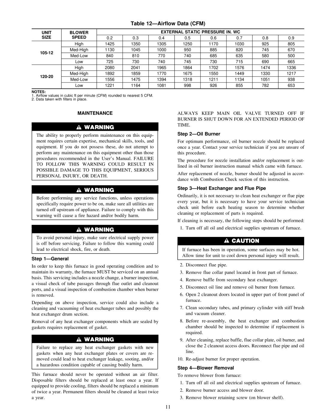
Table 12—Airflow Data (CFM)
UNIT | BLOWER |
|
| EXTERNAL STATIC PRESSURE IN. WC |
|
| ||||
SIZE | SPEED | 0.2 | 0.3 | 0.4 | 0.5 | 0.6 | 0.7 | 0.8 | 0.9 | |
|
|
|
|
|
|
|
|
|
| |
| High | 1425 | 1350 | 1305 | 1250 | 1170 | 1030 | 925 | 805 | |
|
|
|
|
|
|
|
|
|
| |
1130 | 1045 | 1000 | 950 | 885 | 820 | 745 | 670 | |||
|
|
|
|
|
|
|
|
| ||
840 | 810 | 770 | 740 | 685 | 635 | 580 | 500 | |||
| ||||||||||
|
|
|
|
|
|
|
|
|
| |
| Low | 725 | 730 | 740 | 745 | 730 | 715 | 690 | 665 | |
|
|
|
|
|
|
|
|
|
| |
| High | 2080 | 2041 | 1965 | 1864 | 1702 | 1576 | 1474 | 1336 | |
|
|
|
|
|
|
|
|
|
| |
1892 | 1859 | 1770 | 1675 | 1550 | 1449 | 1330 | 1217 | |||
|
|
|
|
|
|
|
|
| ||
1556 | 1475 | 1394 | 1318 | 1211 | 1134 | 1051 | 938 | |||
| ||||||||||
|
|
|
|
|
|
|
|
|
| |
| Low | 1221 | 1164 | 1081 | 998 | 926 | 855 | 782 | 653 | |
|
|
|
|
|
|
|
|
|
| |
NOTES:
1.Airflow values in cubic ft per minute (CFM) rounded to nearest 5 CFM.
2.Data taken with filters in place.
MAINTENANCE
The ability to properly perform maintenance on this equip- ment requires certain expertise, mechanical skills, tools, and equipment. If you do not possess these, do not attempt to perform any maintenance on this equipment other than those procedures recommended in the User’s Manual. FAILURE TO FOLLOW THIS WARNING COULD RESULT IN POSSIBLE DAMAGE TO THIS EQUIPMENT, SERIOUS PERSONAL INJURY, OR DEATH.
Before performing any service functions, unless operations specifically require power to be on, make sure all utilities are turned off upstream of appliance. Failure to comply with this warning will cause a fire hazard and/or bodily harm.
To avoid personal injury, make sure electrical supply power is off before servicing. Failure to follow this warning could lead to electrical shock, fire, or death.
Step 1—General
In order to keep this furnace in good operating condition and to maintain its warranty, the furnace MUST be serviced on an annual basis. This servicing includes a nozzle change, a burner inspection, a visual check of tube passages through flue outlet and cleanout ports, and a visual inspection of combustion chamber when burner is removed.
Depending on above inspection, service could also include a cleaning and vacuuming of heat exchanger tubes and possibly the heat exchanger drum section.
Removal of any heat exchanger components which are sealed by gaskets requires replacement of gasket.
Failure to replace any heat exchanger gaskets with new gaskets when any heat exchanger plates or covers are re- moved could lead to heat exchanger leakage, sooting, and/or a hazardous condition capable of causing bodily harm.
This furnace should never be operated without an air filter. Disposable filters should be replaced at least once a year. If equipped to provide cooling, filters should be replaced a minimum of twice a year. Permanent filters should be cleaned at least twice a year.
ALWAYS KEEP MAIN OIL VALVE TURNED OFF IF BURNER IS SHUT DOWN FOR AN EXTENDED PERIOD OF TIME.
Step 2—Oil Burner
For optimum performance, oil burner nozzle should be replaced once a year. Contact your service technician if you are unsure of this procedure.
The procedure for nozzle installation and/or replacement is out- lined in oil burner instruction manual which came with furnace.
After replacement of nozzle, burner should be adjusted in accor- dance with Combustion Check section of this instruction.
Step 3—Heat Exchanger and Flue Pipe
Ordinarily, it is not necessary to clean heat exchanger or flue pipe every year, but it is necessary to have your service technician check unit before each heating season to determine whether cleaning or replacement of parts is required.
If cleaning is necessary, the following steps should be performed:
1. Turn off all oil and electrical supplies upstream of furnace.
If furnace has been in operation, some surfaces may be hot. Allow time for unit to cool down personal injury will result.
2.Disconnect flue pipe.
3.Remove flue collar panel located in front part of furnace.
4.Remove baffle from secondary heat exchanger.
5.Disconnect oil line and remove oil burner from furnace.
6.Open 2 cleanout doors located in upper part of front panel of furnace.
7.Clean secondary tubes, and primary cylinder with stiff brush and vacuum cleaner.
8.Before
9.After cleaning, replace baffle, flue collar plate, oil burner, and close the 2 cleanout access doors. Reconnect flue pipe and oil line.
10.
Step 4—Blower Removal
To remove blower from furnace:
1.Turn off all oil and electrical supplies upstream of furnace.
2.Remove burner access and blower door.
3.Remove blower retaining screw (on blower shelf).
11