TEST/TWIN
COM W Y R G 24V
HUM ![]()
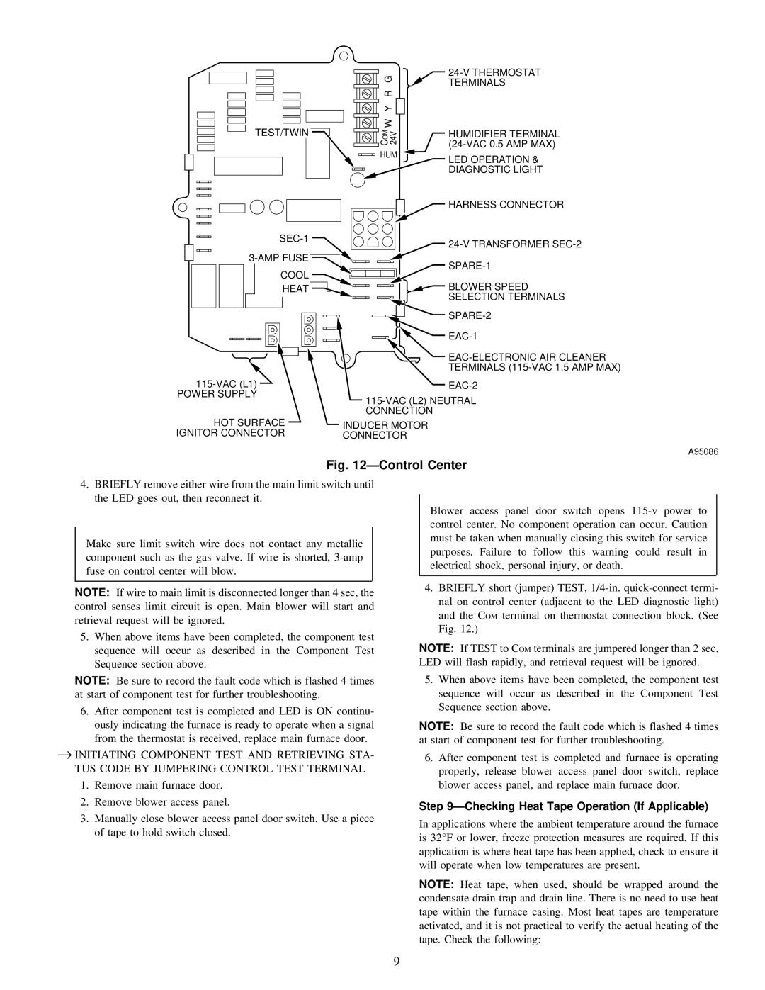
HUMIDIFIER TERMINAL
LED OPERATION & DIAGNOSTIC LIGHT
| HARNESS CONNECTOR | |
| ||
COOL | ||
BLOWER SPEED | ||
HEAT | ||
| SELECTION TERMINALS | |
| ||
| ||
| ||
| TERMINALS | |
POWER SUPPLY | ||
| ||
| CONNECTION | |
HOT SURFACE | INDUCER MOTOR | |
IGNITOR CONNECTOR | CONNECTOR |
A95086
Fig. 12ÐControl Center
4.BRIEFLY remove either wire from the main limit switch until the LED goes out, then reconnect it.
Make sure limit switch wire does not contact any metallic component such as the gas valve. If wire is shorted,
NOTE: If wire to main limit is disconnected longer than 4 sec, the control senses limit circuit is open. Main blower will start and retrieval request will be ignored.
5.When above items have been completed, the component test sequence will occur as described in the Component Test Sequence section above.
NOTE: Be sure to record the fault code which is flashed 4 times at start of component test for further troubleshooting.
6.After component test is completed and LED is ON continu- ously indicating the furnace is ready to operate when a signal from the thermostat is received, replace main furnace door.
→INITIATING COMPONENT TEST AND RETRIEVING STA- TUS CODE BY JUMPERING CONTROL TEST TERMINAL
1.Remove main furnace door.
2.Remove blower access panel.
3.Manually close blower access panel door switch. Use a piece of tape to hold switch closed.
Blower access panel door switch opens
4.BRIEFLY short (jumper) TEST,
NOTE: If TEST to COM terminals are jumpered longer than 2 sec, LED will flash rapidly, and retrieval request will be ignored.
5.When above items have been completed, the component test sequence will occur as described in the Component Test Sequence section above.
NOTE: Be sure to record the fault code which is flashed 4 times at start of component test for further troubleshooting.
6.After component test is completed and furnace is operating properly, release blower access panel door switch, replace blower access panel, and replace main furnace door.
Step 9ÐChecking Heat Tape Operation (If Applicable)
In applications where the ambient temperature around the furnace is 32°F or lower, freeze protection measures are required. If this application is where heat tape has been applied, check to ensure it will operate when low temperatures are present.
NOTE: Heat tape, when used, should be wrapped around the condensate drain trap and drain line. There is no need to use heat tape within the furnace casing. Most heat tapes are temperature activated, and it is not practical to verify the actual heating of the tape. Check the following:
9