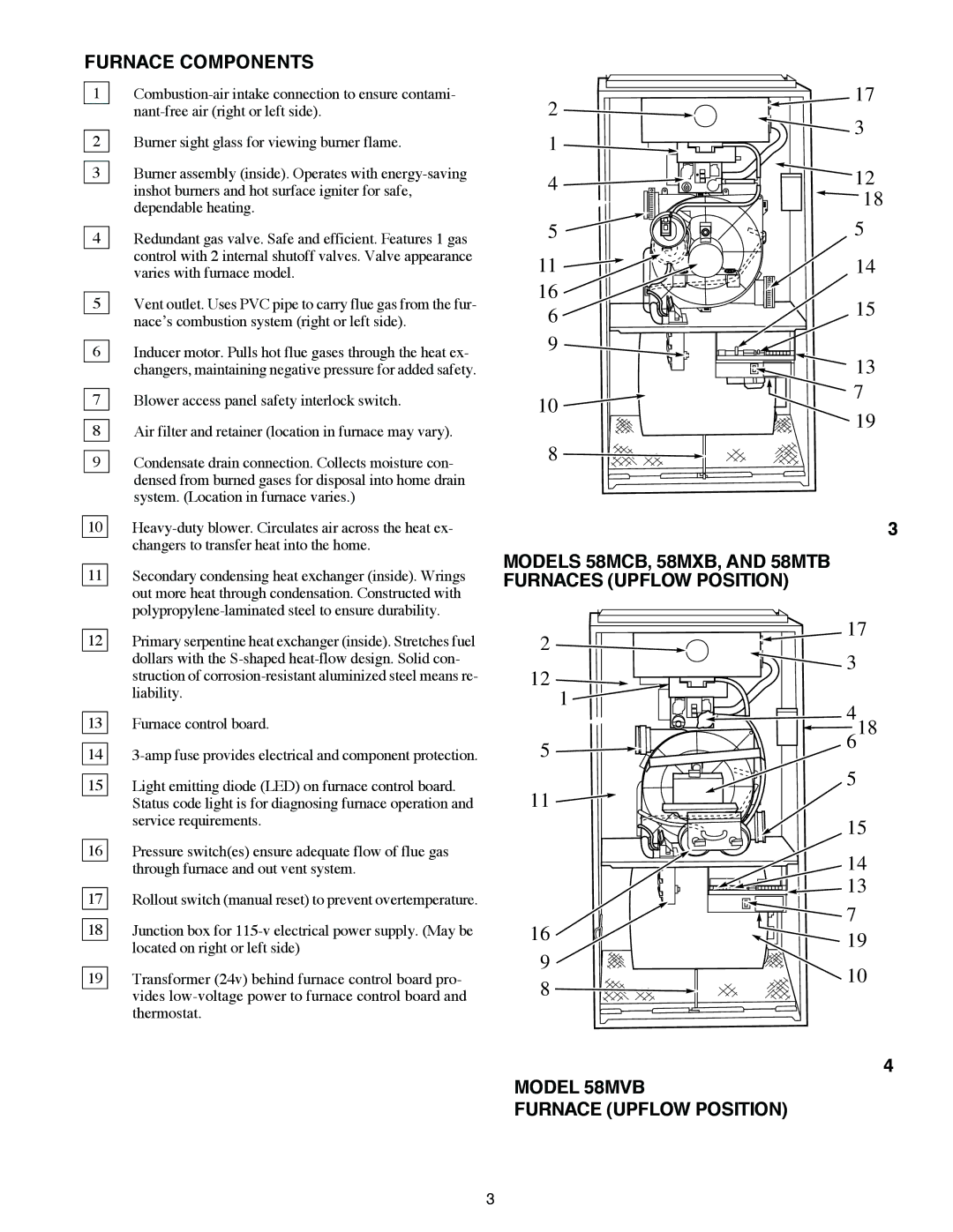
FURNACE COMPONENTS
1
2Burner sight glass for viewing burner flame.
3Burner assembly (inside). Operates with
4Redundant gas valve. Safe and efficient. Features 1 gas control with 2 internal shutoff valves. Valve appearance varies with furnace model.
5Vent outlet. Uses PVC pipe to carry flue gas from the fur- nace’s combustion system (right or left side).
6Inducer motor. Pulls hot flue gases through the heat ex- changers, maintaining negative pressure for added safety.
7Blower access panel safety interlock switch.
8Air filter and retainer (location in furnace may vary).
9Condensate drain connection. Collects moisture con- densed from burned gases for disposal into home drain system. (Location in furnace varies.)
10 | |
| changers to transfer heat into the home. |
|
|
11 | Secondary condensing heat exchanger (inside). Wrings |
| out more heat through condensation. Constructed with |
|
2 | 17 | |
3 | ||
1 | ||
| ||
4 | 12 | |
| 18 | |
5 | 5 | |
11 | 14 | |
16 | 15 | |
6 | ||
| ||
9 |
| |
| 13 | |
10 | 7 | |
19 | ||
| ||
8 |
|
3
MODELS 58MCB, 58MXB, AND 58MTB
FURNACES (UPFLOW POSITION)
12 | Primary serpentine heat exchanger (inside). Stretches fuel |
| dollars with the |
| struction of |
| liability. |
2 ![]()
12 ![]()
1
17
![]() 3
3
13 | Furnace control board. |
|
|
14 | |
|
|
15 | Light emitting diode (LED) on furnace control board. |
| Status code light is for diagnosing furnace operation and |
| service requirements. |
|
|
16 | Pressure switch(es) ensure adequate flow of flue gas |
| through furnace and out vent system. |
|
|
17 | Rollout switch (manual reset) to prevent overtemperature. |
|
|
18 | Junction box for |
| located on right or left side) |
|
|
19 | Transformer (24v) behind furnace control board pro- |
| vides |
| thermostat. |
| 4 |
5 | 618 |
| |
11 | 5 |
|
| 15 | |
| 14 | |
| 13 | |
16 | 7 | |
19 | ||
9 | ||
10 | ||
8 | ||
|
4
MODEL 58MVB
FURNACE (UPFLOW POSITION)
3