To 24VAC

Power

To Equipment

Rz

C

Rc/Rh

Twist Of f

Rh

Rc

Y1

W1

G

Fuse

Relay

Relay

Power Supply


Relay

Zone

R

C

Y1 To Zone

Thermostat

W1

G

To Zone 1 Damper

To Zone 2 Damper

To Zone 3 Damper

CLS_1 COM_1 OPN_1

CLS_ 2 COM_2 OPN_ 2

CLS_ 3 COM_3 OPN_ 3

Triac

Triac

Triac

Triac

Triac

Damper 1

Damper 2

Damper 3

Programming

Connector

Micro

Zone

R


C

To Zone

Y1

Thermostat

W1


G


Zone

R

C To Zone

To LAT Sensor

LAT

LATC

Triac

Status Y1 W G

ON

1 2 3 4 5 6 7

Dipswitches 1-8

Y1 Thermostat

W1

G

Compressor

Timer Override

A04192

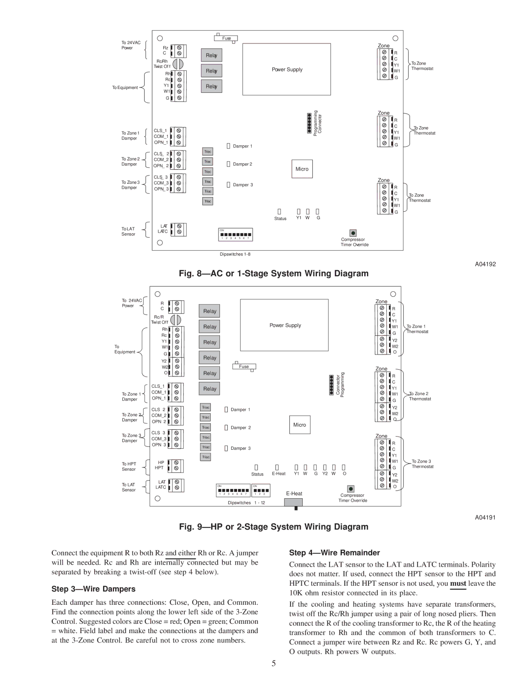
Fig. 8—AC or 1-Stage System Wiring Diagram

To 24VAC

Power

To Equipment

R

C

Rc/R

Twist Of f

Rh

Rc

Y1

W1

G

Y2

Relay

Relay

Power Supply


Relay

Relay

Zone

R

C

Y1

W1 To Zone 1

G

Thermostat

Y2


W2


O


To Zone 1 Damper

To Zone 2 Damper

W2

O

CLS_1 COM_1 OPN_1

CLS 2 COM_2 OPN 2

CLS 3


Relay


Fuse


Relay


Triac


Damper 1


Triac


Triac

Damper 2

Connector

Programming

Micro

Zone

R


C


Y1


W1

To Zone 2

G

Thermostat


Y2


W2


O


To Zone 3 Damper

To HPT

Sensor

To LAT

Sensor

COM_3 OPN 3

HP

HPT

LAT

LATC

Triac

Triac

Damper 3


Triac


Status E-Heat Y1 W G Y2 W O

ON


ON


1

2

3 4 5 6 7

1

2

3

E-Heat

Compressor


Dipswitches

1 - 12


Timer Override


Zone

R


C


Y1


W1

To Zone 3

G

Thermostat


Y2


W2


O


A04191

Fig. 9—HP or 2-Stage System Wiring Diagram

Connect the equipment R to both Rz and either Rh or Rc. A jumper will be needed. Rc and Rh are internally connected but may be separated by breaking a twist-off (see step 4 below).

Step 3—Wire Dampers

Each damper has three connections: Close, Open, and Common. Find the connection points along the lower left side of the 3-Zone Control. Suggested colors are Close = red; Open = green; Common

=white. Field label and make the connections at the dampers and at the 3-Zone Control. Be careful not to cross zone numbers.

Step 4—Wire Remainder

Connect the LAT sensor to the LAT and LATC terminals. Polarity does not matter. If used, connect the HPT sensor to the HPT and HPTC terminals. If the HPT sensor is not used, you must leave the 10K ohm resistor connected in its place.

If the cooling and heating systems have separate transformers, twist off the Rc/Rh jumper using a pair of long nosed pliers. Then connect the R of the cooling transformer to Rc, the R of the heating transformer to Rh and the common of both transformers to C. Connect a jumper wire between Rz and Rc. Rc powers G, Y, and O outputs. Rh powers W outputs.

5

Page 5
Image 5
Carrier ZONECC3Z instruction manual Wire Dampers, Wire Remainder, A04192, A04191

ZONECC3Z specifications

The Carrier ZONECC3Z is a cutting-edge climate control solution that has made a significant impact in the HVAC (heating, ventilation, and air conditioning) industry. As a versatile and efficient system, the ZONECC3Z is particularly designed to address the specific needs of residential and commercial spaces, providing unparalleled comfort while optimizing energy usage.

One of the main features of the ZONECC3Z is its advanced zoning capabilities. This system allows users to create separate temperature zones within a building, ensuring that each area can be heated or cooled according to its unique requirements. This not only enhances comfort but also improves energy efficiency, as only the zones that require climate control are actively managed. With this system, occupants can enjoy personalized comfort in different rooms or areas, reducing energy waste and costs.

Incorporating state-of-the-art technology, the ZONECC3Z is equipped with smart controls that enable intuitive management of the system. Users can monitor and adjust settings remotely through a user-friendly mobile app or a web-based interface. This connectivity feature allows for seamless integration with smart home devices and automation systems, enhancing user convenience and enabling proactive energy management.

Another key characteristic of the ZONECC3Z is its variable-speed compressor technology. This feature allows the system to adjust its cooling and heating output dynamically, responding to real-time temperature changes. This results in a quieter operation and greater efficiency, as the system avoids the on-and-off cycling common in traditional HVAC units. Consequently, users benefit from consistent indoor temperatures and lower utility bills.

The ZONECC3Z is also designed with sustainability in mind. It employs eco-friendly refrigerants that significantly reduce greenhouse gas emissions. With energy efficiency ratings that often exceed industry standards, this system can play a vital role in reducing the carbon footprint of buildings, making it an attractive option for environmentally conscious consumers.

In summary, the Carrier ZONECC3Z stands out as a powerful, efficient, and flexible solution for modern climate control needs. Its zoning capabilities, smart technology integration, variable-speed operation, and commitment to sustainability make it an ideal choice for both residential and commercial applications. Whether it’s for a home seeking comfort or a business aiming for cost-effective energy management, the ZONECC3Z delivers exceptional performance and peace of mind.