Page 6 of 12 |
ELECTRICAL CONNECTIONS
Connections are made using pressure terminal connectors. Legends on the unit identify each terminal function. Attach leads by stripping 3/8", inserting into connector and clamp by tightening screw. Make sure the screw is tight and the wire can't be pulled out. Failure to adequately tighten the screw can result in improper operation or burning the connector and wire.
Positive Supply: Due to the high current nature of this unit, an appropriate supply line is required. In addition to the high current delivered to devices on the out- puts, the siren amplifier will require peak currents up to 50 amps for ade- quate short circuit protection and reliable operation. The preferred source is directly at the vehicle battery.
Negative Supply: The negative supply line is for the siren amplifier. The siren amplifier will require peak currents up to 50 amps for adequate short circuit protection and reliable operation. The preferred source is directly at the vehicle bat- tery.
Speaker:Both connections must be used. Two speakers may be connected in par- allel. Observe polarity (phasing) for maximum sound output.
Radio (Optional): Both connections must be used. The input is isolated and polarity is not important. May need to adjust RADIO VOLUME on side of amplifier.
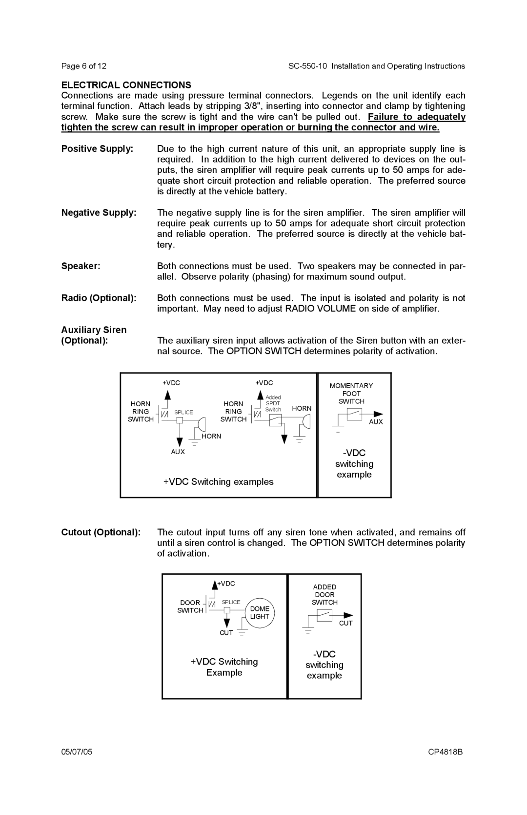
Auxiliary Siren
(Optional): The auxiliary siren input allows activation of the Siren button with an exter- nal source. The OPTION SWITCH determines polarity of activation.
HORN
RING
SWITCH
+VDC
HORN
SPLICERING
SWITCH
HORN
AUX
+VDC
![]() Added
Added
SPDT
Switch HORN
MOMENTARY
FOOT
SWITCH
AUX
-VDC
+VDC Switching examples
switching example
Cutout (Optional): The cutout input turns off any siren tone when activated, and remains off until a siren control is changed. The OPTION SWITCH determines polarity of activation.
|
|
| +VDC | ||||||||||
DOOR |
|
| SPLICE | ||||||||||
SWITCH |
|
|
|
|
|
|
|
|
|
|
|
| DOME |
|
|
|
|
|
|
|
|
| |||||
|
|
|
|
|
|
|
|
|
|
|
|
| LIGHT |
|
|
| CUT |
|
|
|
|
|
| ||||
|
|
|
|
|
|
|
|
| |||||
|
|
|
|
|
|
|
|
|
|
|
|
|
|
+VDC Switching
Example
ADDED
DOOR
SWITCH
CUT
switching example
05/07/05 | CP4818B |