Page 5 of 12 |
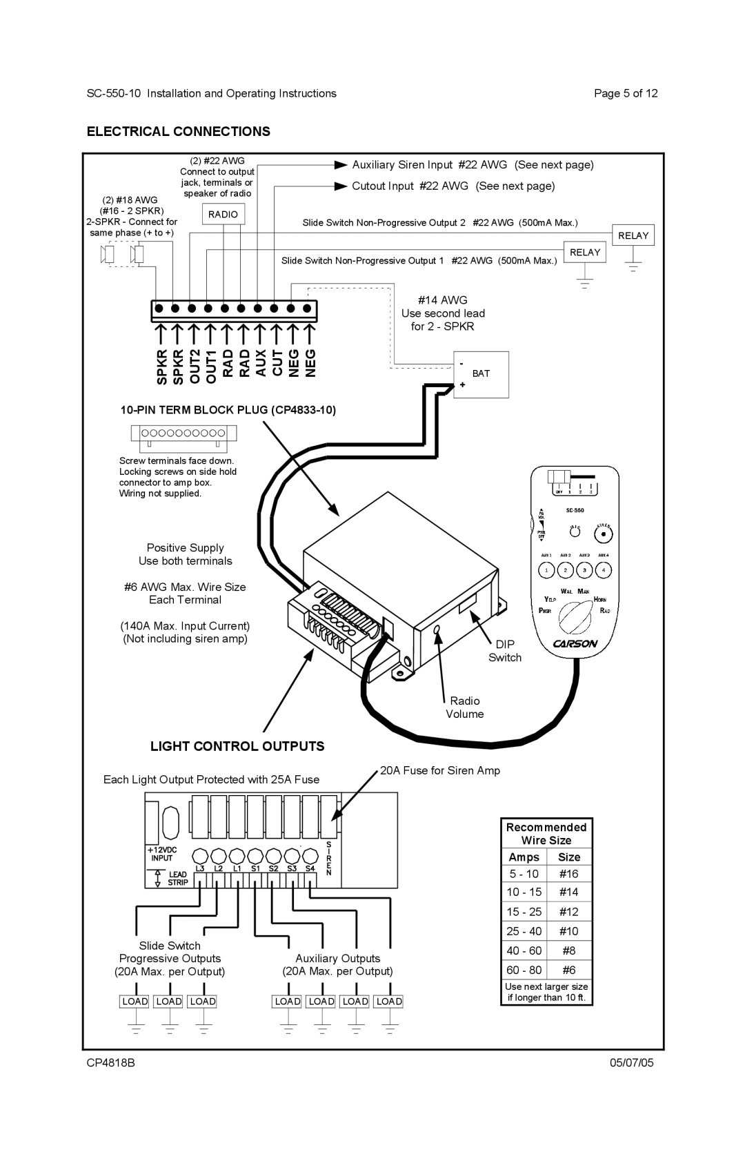
ELECTRICAL CONNECTIONS
(2)#18 AWG (#16 - 2 SPKR)
(2) #22 AWG |
|
| Auxiliary Siren Input #22 AWG (See next page) | |||||||||
Connect to output |
|
|
|
|
|
|
|
|
| |||
jack, terminals or |
|
| Cutout Input #22 AWG (See next page) | |||||||||
speaker of radio |
|
|
|
|
|
|
|
|
| |||
|
| RADIO |
|
| Slide Switch | |||||||
|
|
|
|
| ||||||||
|
|
|
| |||||||||
|
|
|
|
|
|
|
|
|
|
|
|
|
|
|
|
|
|
|
| RELAY | |||||
|
|
|
|
| Slide Switch | |||||||
|
|
|
|
|
|
|
|
|
|
| ||
|
|
|
|
|
|
|
|
|
|
|
|
|
|
|
|
|
|
|
|
|
|
|
|
|
|
RELAY |
![]() • • • • • • • • • •
• • • • • • • • • •![]()
![]()
SPKR → SPKR → OUT2 → OUT1 → RAD → RAD → AUX → CUT → NEG → NEG →
Screw terminals face down. Locking screws on side hold connector to amp box.
Wiring not supplied.
#14 AWG
Use second lead
for 2 - SPKR
-
BAT
![]() +
+
Positive Supply
Use both terminals
#6 AWG Max. Wire Size
Each Terminal
(140A Max. Input Current)
(Not including siren amp)![]() DIP
DIP
Switch
Radio
Volume
LIGHT CONTROL OUTPUTS
Each Light Output Protected with 25A Fuse
20A Fuse for Siren Amp
Slide Switch
Progressive Outputs (20A Max. per Output)
LOAD![]()
![]() LOAD
LOAD![]()
![]() LOAD
LOAD
Auxiliary Outputs
(20A Max. per Output)
LOAD![]()
![]() LOAD
LOAD![]()
![]() LOAD
LOAD![]()
![]() LOAD
LOAD
Recommended
Wire Size
Amps Size
5 - 10 #16
10 - 15 #14
15 - 25 #12
25 - 40 #10
40 - 60 #8
60 - 80 #6
Use next larger size if longer than 10 ft.
CP4818B | 05/07/05 |