Pickup Wiring Conversion
Side 1 Side 2
D
![]()
![]() H
H
S | ||
i | ||
d | ||
| e | |
|
| 1 |
| ||
|
| S |
|
| |
|
| i |
|
| d |
|
| e |
2 | ||
C
B
A
![]()
![]() G
G
![]()
![]() F
F
![]()
![]() E
E
D | C |
|
|
|
|
|
|
| B |
|
|
|
|
| |
|
| A |
|
|
|
| |
|
|
| H |
|
|
| |
|
|
|
| G |
|
| |
|
|
|
|
| F |
| |
|
|
|
|
|
| E | |
|
|
|
|
|
|
|
3Way
Standard “ Fender”Type
Open Frame Switch
3 Way
Inline “Carvin”Type Switch
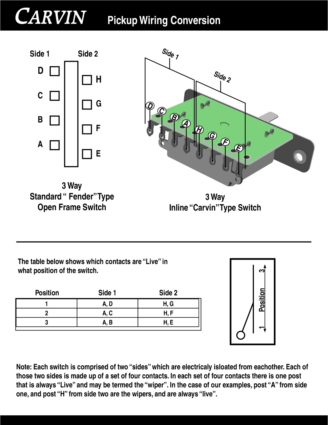
The table below shows which contacts are “Live” in what position of the switch.
Position | Side 1 | Side 2 |
|
|
|
|
|
1 | A, D | H, G |
|
2 | A, C | H, F |
|
3 | A, B | H, E |
|
|
|
|
|
1 Position 3
Note: Each switch is comprised of two “sides” which are electricaly isloated from eachother. Each of those two sides is made up of a set of four contacts. In each set of four contacts there is one post that is always “Live” and may be termed the “wiper”. In the case of our examples, post “A” from side one, and post “H” from side two are the wipers, and are always “live”.
