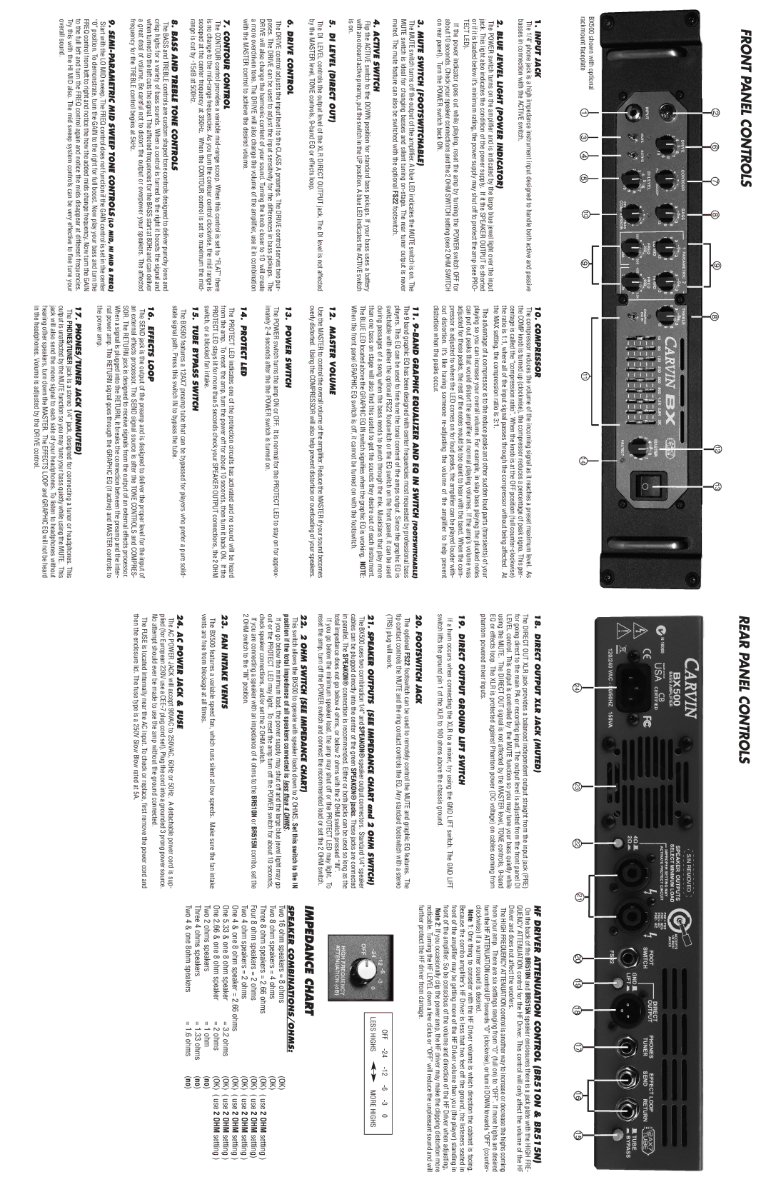
FRONT PANEL CONTROLS
2 | 6 | 7 | 8 | 9 | 8 | 12 | 13 |
BX500 shown with optional | 1 | 3 | 4 | 5 | 10 | 9 | 11 |
|
rackmount faceplate | 14 |
REAR PANEL CONTROLS
24 | 23 | 22 | 21 | 20 | 19 | 18 | 17 | 16 | 15 |
1.INPUT JACK
The 1/4" phone jack is a high impedance instrument input designed to handle both active and passive basses in connection with the ACTIVE switch.
2. BLUE JEWEL LIGHT (POWER INDICATOR)
The POWER switch turns on the amplifier and is indicated by the large blue jewel light over the input jack. This light also indicates the condition of the power supply. If it the SPEAKER OUTPUT is shorted or if it is loaded below it’s minimum rating, the power supply may shut off to protect the amp (see PRO- TECT LED).
If the power indicator goes out while playing, reset the amp by turning the POWER switch OFF for about 10 seconds. Check your speaker connections and the 2 OHM SWITCH setting (see 2 OHM SWITCH on rear panel). Turn the POWER switch back ON.
3. MUTE SWITCH (FOOTSWITCHABLE)
The MUTE switch turns off the output of the amplifier. A blue LED indicates the MUTE switch is on. The MUTE switch is ideal for changing basses and silent tuning
10. COMPRESSOR
The compressor reduces the volume of the incoming signal as it reaches a preset maximum level. As the COMP knob is turned up (clockwise), the compressor reduces a percentage of peak signa. This per- centage is called the “compression ratio”. When the knob is at the OFF position (full
The advantage of a compressor is to the reduce peaks and other sudden loud parts (transients) of your playing so you can increase your overall volume. For example, in slap bass playing the plucked notes can put out peaks that would distort the amplifier at normal playing volumes. If the amp’s volume was adjusted for these peaks, the rest of the notes would be too quiet to hear with the band. When the com- pressor is adjusted to where the LED comes on for loud peaks, the amplifier can be played louder with- out distortion. It’s like having someone
11. |
The 9 band graphic EQ has been designed with center frequencies most requested by professional bass |
players. This EQ can be used to fine tune the tonal content of the amps output. Since the graphic EQ is |
18. DIRECT OUTPUT XLR JACK (MUTED)
The DIRECT OUT XLR jack provides a balanced independent output straight from the input jack (PRE) for going direct to the main PA or recording input. The output level is adjusted from the front panel DI LEVEL control. This output is controlled by the MUTE function so you may tune your bass quietly while using the MUTE. The DIRECT OUT signal is not affected by the MASTER level, TONE controls,
19. DIRECT OUTPUT GROUND LIFT SWITCH
If a hum occurs when connecting the XLR to a mixer, try using the GND LIFT switch. The GND LIFT switch lifts the ground pin 1 of the XLR to 100 ohms above the chassis ground.
20. FOOTSWITCH JACK
The optional FS22 footswitch can be used to remotely control the MUTE and graphic EQ features. The tip contact controls the MUTE and the ring contact controls the EQ. Any standard footswitch with a stereo
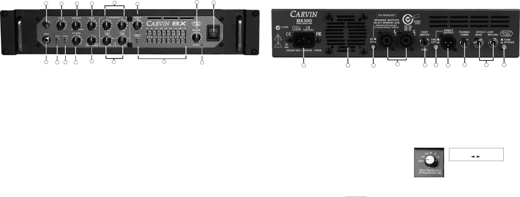
HF DRIVER ATTENUATION CONTROL (BR510N & BR515N)
On the back of the BR510N and BR515N speaker enclosures there is a jack plate with the HIGH FRE- QUENCY ATTENUATION control for the HF Driver. This control will only affect the volume of the HF Driver and does not affect the woofers.
The HIGH FREQUENCY ATTENUATION control is another way to increase or decrease the highs coming from your amp. There are six settings ranging from “0” (full on) to “OFF”. If more highs are desired turn the HF ATTENUATION control UP towards “0” (clockwise), or turn it DOWN towards “OFF” (counter- clockwise) if a warmer sound is desired.
Note 1: One thing to consider with the HF Driver volume is which direction the cabinet is facing. Because the combo amplifier’s HF Driver is less that two feet off the ground, the listeners seated in front of the amplifier may be getting more of the HF Driver volume than you (the player) standing in front of the amplifier. So be conscious of the volume and direction of the HF Driver when adjusting.
Note 2: If you occasionally clip the power amp, the HF driver may make the clipping distortion more noticable. Turning the HF LEVEL down a few clicks or “OFF” will reduce the unpleasant sound and will further protect the HF driver from damage.
4. ACTIVE SWITCH
Flip the ACTIVE switch to the DOWN position for standard bass pickups. If your bass uses a battery with an onboard active preamp, put the switch in the UP position. A blue LED indicates the ACTIVE switch is on.
5. DI LEVEL (DIRECT OUT)
The DI LEVEL controls the output level of the XLR DIRECT OUTPUT jack. The DI level is not affected
switchable with either the optional FS22 footswitch or the EQ switch on the front panel, it can be used |
during passages of a song when the bass needs to punch through the mix. Musicians that play more |
than one bass on stage will also find this useful to get the sounds they desire out of each instrument. |
The BLUE LED located above the GRAPHIC EQ IN switch signifies when the graphic EQ is working. NOTE: |
When the front panel GRAPHIC EQ switch is off, it cannot be turned on with the footswitch. |
12. MASTER VOLUME |
Use the MASTER to control the overall volume of the amplifier. Reduce the MASTER if your sound becomes
(TRS) plug will work.
21.SPEAKER OUTPUTS (SEE IMPEDANCE CHART and 2 OHM SWITCH)
The BX500 uses two combination 1/4” and SPEAKON® speaker output connectors. Standard 1/4” speaker
cables can be plugged directly into the center of the green SPEAKON® jacks. These jacks are connected in parallel. The SPEAKON® connection is recommended. Either or both jacks can be used so long as the total impedance does not go below 4 ohms, or below 2 ohms with the 2 OHM switch pressed “IN”.
If you go below the minimum speaker load, the amp may shut off or the PROTECT LED may light. To reset the amp, turn off the POWER switch and connect the recommended load or set the 2 OHM switch.
OFF
LESS HIGHS |
| MORE HIGHS |
|
by the MASTER level, TONE controls,
6. DRIVE CONTROL
The DRIVE control adjusts the input level to the CLASS A preamps. The DRIVE control serves two pur- poses. The DRIVE can be used to adjust the input sensitivity for the differences in bass pickups. The DRIVE will also change the harmonic content of your sound. Turning the knob closer to 10 will create a more overdriven tone. The DRIVE will also change the volume of the amplifier, use it in combination with the MASTER control to achieve the desired volume.
7. CONTOUR CONTROL
The CONTOUR control provides a variable
8. BASS AND TREBLE TONE CONTROLS
The BASS and TREBLE controls are custom shaped tone controls designed to deliver punchy lows and crisp highs for a variety of bass sounds. When a control is turned to the right it boosts the signal and when turned to the left cuts the signal. The affected frequencies for the BASS start at 80Hz and can deliver a great deal of volume. Be careful not to distort the output or overpower your speakers. The affected frequency for the TREBLE control begins at 5kHz.
9.
Start with the LO MID sweep. The FREQ control does not function if the GAIN control is set in the center
“0” position. To demonstrate, turn the GAIN to the right for full boost. Now play your bass and turn the FREQ control from left to right and notice the how the added mids change frequency. Now turn the GAIN to the full left and turn the FREQ control again and notice the mids disappear at different frequencies. Try this with the HI MID also. The mid sweep system controls can be very effective to fine tune your overall sound.
overly distorted. Using the COMPRESSOR will also help prevent distortion or overloading of your speakers.
13. POWER SWITCH
The POWER switch turns the amp ON or OFF. It is normal for the PROTECT LED to stay on for approx- imately
14. PROTECT LED
The PROTECT LED indicates one of the protection circuits has activated and no sound will be heard from the amp. To reset the amp, turn the power off for about 10 seconds, then turn it back ON. If the PROTECT LED stays lit for more than 5 seconds check your SPEAKER OUTPUT connections, the 2 OHM switch, or a blocked fan intake.
15. TUBE BYPASS SWITCH
The BX500 features a 12AX7 preamp tube that can be bypassed for players who prefer a pure solid- state signal path. Press this switch IN to bypass the tube.
16. EFFECTS LOOP
The SEND jack is the output of the preamp and is designed to deliver the proper level for the input of an external effects processor. The SEND signal source is after the TONE CONTROLS and COMPRES- SOR. The RETURN jack is designed to receive signals from the output of an external effects processor. When a signal is plugged into the RETURN, it breaks the connection between the preamp and the inter- nal power amp. The RETURN signal goes through the GRAPHIC EQ (if active) and MASTER controls to the power amp.
17. PHONES/TUNER JACK (UNMUTED)
The PHONES/TUNER jack is a stereo 1/4” jack, designed for connecting a tuner or headphones. This output is unaffected by the MUTE function so you may tune your bass quietly while using the MUTE. This jack will also send the mono signal to each side of your headphones. To listen to headphones without hearing other speakers, turn down the MASTER. The EFFECTS LOOP and GRAPHIC EQ will not be heard in the headphones. Volume is adjusted by the DRIVE control.
22. 2 OHM SWITCH (SEE IMPEDANCE CHART)
This switch allows the BX500 to operate with speaker loads down to 2 OHMS. Set this switch to the IN position if the total impedance of all speakers connected is less than 4 OHMS.
If you go below the minimum load, the power supply may shut off and the large blue jewel light may go out or the PROTECT LED may light. To reset the amp turn off the POWER switch for about 10 seconds, check speaker connections, and/or set the 2 OHM switch.
If you are connecting a speaker with an impedance of 4 ohms to the BR510N or BR515N combo, set the 2 OHM switch to the “IN” position.
23. FAN INTAKE VENTS
The BX500 features a variable speed fan, which runs silent at low speeds. Make sure the fan intake vents are free from blockage at all times.
24. AC POWER JACK & FUSE
The AC POWER JACK will accept 90VAC to 250VAC, 60Hz or 50Hz. A detachable power cord is sup- plied (for European 230V use a
The FUSE is located internally near the AC input. To check or replace, first remove the power cord and then the enclosure lid. The fuse type is a 250V Slow Blow rated at 5A.
IMPEDANCE CHART
SPEAKER COMBINATIONS/OHMS: | (OK) | ||
Two 16 ohm speakers = 8 ohms |
|
| |
Two 8 ohm speakers = 4 ohms |
|
| (OK) |
Three 8 ohm speakers = 2.66 ohms |
|
| (OK) ( use 2 OHM setting ) |
Four 8 ohm speakers = 2 ohms |
|
| (OK) ( use 2 OHM setting) |
Two 4 ohm speakers = 2 ohms |
|
| (OK) ( use 2 OHM setting ) |
One 4 & one 8 ohm speaker = 2.66 ohms | (OK) ( use 2 OHM setting ) | ||
One 5.33 & one 8 ohm speaker | = 3.2 ohms | (OK) ( use 2 OHM setting ) | |
One 2.66 & one 8 ohm speaker | = 2 ohms | (OK) ( use 2 OHM setting ) | |
Two 2 ohms speakers | = 1 ohm | (no) | |
Three 4 ohms speakers | = 1.33 ohms | (no) | |
Two 4 & one 8ohm speakers | = 1.6 ohms | (no) | |