EX-S20U/EX-M20U
Unpacking
Introduction
Contents
Basic Image Recording
Deleting Files
Using a Memory Card
Playing Back Audio Files 159
Playing AN Audio File EX-M20U Only
Copyright Restrictions
SD logo is a registered trademark
Bestshot
Features
Introduction
General Precautions
Precautions
EX-M20U Only
Introduction
Operating conditions
Data Error Precautions
Lens
Condensation
Other
Quick Start Guide
First, charge the battery
4, 5, 6, 7, 8
To configure display language and clock settings
To view a recorded image
To record an image
Press SET to delete the image
To delete an image
About This Manual
Getting Ready
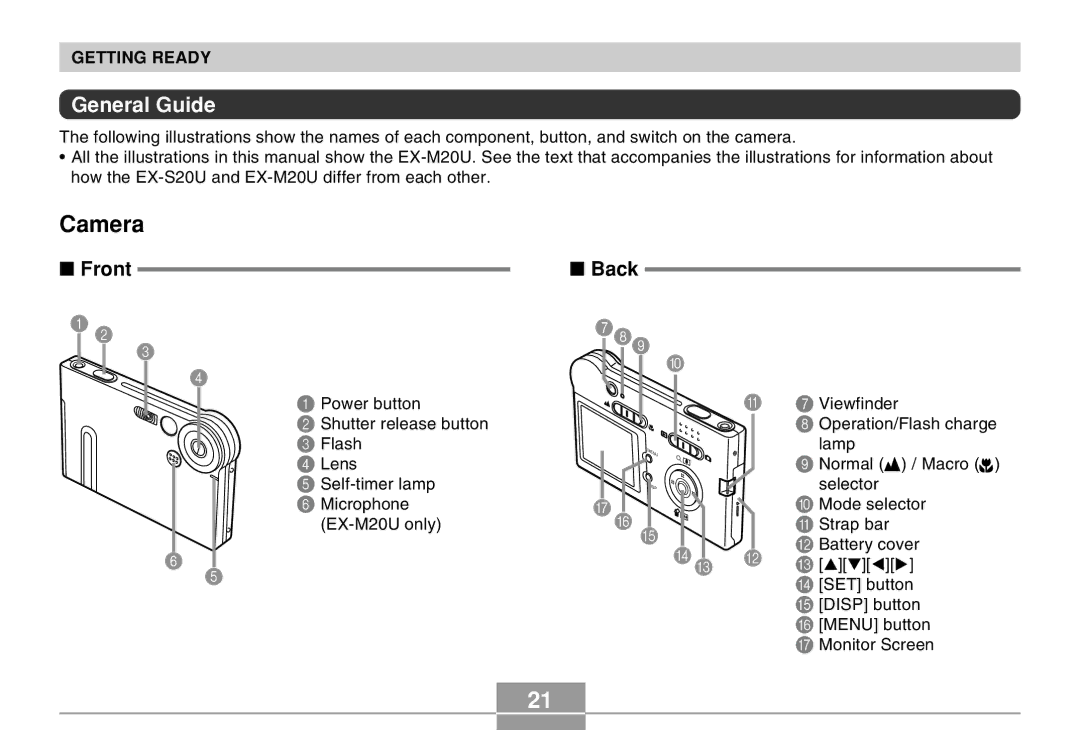
General Guide
Camera
Front
Back
Bottom
USB Cradle
Monitor Screen Contents
REC mode
Play mode
Changing the Contents of the Monitor Screen
To load the battery
Power Requirements
Attaching the Strap
Arrow marks NP-20
Turn off the camera Set the camera onto the USB cradle
To charge the battery
Getting Ready
Battery Life Guidelines
If the camera works normally
If the camera does not work normally
Low Battery Indicator
Tip to Make the Battery Last Longer
Battery Handling Precautions
Power Supply Precautions
Precautions During USE
Getting Ready Battery Storage Precautions
USB Cradle and AC Adaptor Precautions
Turning the Camera On and Off
Auto Power Off APO
Using the On-screen Menus
Then align Mode selector with REC to enter REC mode
Turn on the camera
Menu Screen Operations
Use and to change the currently selected setting
Configuring Display Language and Clock Settings
To configure display language and clock settings
Example December 24
Set the current date and the time
Basic Image Recording
Aiming the Camera
Recording an Image
Recording an lmage
Recording Precautions
About the REC Mode Monitor Screen
REC mode, use and to change the digital zoom factor
Using Zoom
Using the Flash
About Red-eye Reduction
Flash Precautions
Recording Macro Images
Align the Normal
Macro selector with
Selecting Off in disables the self-timer
Using the Self-timer
Specifying Image Size and Quality
To specify the image size
To specify image quality
Basic Image Recording
Exposure Compensation EV Shift
Other Recording Functions
Adjusting White Balance
Adjusting White Balance Manually
Using the Bestshot Mode
Example Sample Scene
Press SET
This enters the Bestshot mode and displays a sample scene
Creating Your Own Bestshot Setup
To delete a Bestshot user setup
Record the image
Semi-transparent image
Other Recording Functions
Select the REC tab, select REC Mode,
REC mode, press Menu
Then press
Use and to select Bestshot
Adding Audio to a Snapshot
Recording Audio EX-M20U Only
Press the shutter release button to record the image
Press the shutter release button to start audio recording
Recording Your Voice
Press the shutter release button to start voice recording
Audio Recording Precautions
Using the Histogram
Specifying ISO Sensitivity
REC Mode Camera Settings
Turning the On-screen Grid On and Off
Assigning Functions to Keys
Turning Image Review On and Off
Initial default setting is REC Mode
Specifying Power On Default Settings
Resetting the Camera
Basic Playback Operation
Playback
Playing an Audio Snapshot EX-M20U Only
Flipping the Display
Press Menu to return the image to its original size
Zooming the Display Image
Resizing an Image
Use and to make the cropping boundary smaller or larger
Cropping an Image
Displaying the Calendar Screen
Playing a Slide Show
Configure the slideshow settings
Use and to select Start, and then press SET
To stop Slide Show, press SET
Selecting a Particular Image for a Slideshow
To specify the slideshow images
To set the slideshow interval
To specify the slideshow time
Using the Photo Stand Feature
To stop the Phot Stand slideshow, press Photo again
Press the USB cradle’s Photo button
Rotating the Display Image
Using Image Roulette
Adding Audio to a Snapshot EX-M20U Only
To re-record audio
Playing Back a Voice Recording File EX-M20U Only
Deleting a Single File
Deleting Files
Press SET to delete the file
Press Menu to exit the menu screen
Press SET to delete all the files
Deleting All Files
File Management
Memory Folders and Files
Folders
Protecting Files
To protect a single file
To protect all files in memory
Dpof Settings
To configure print settings for a single image
To configure print settings for all images
100
Print Image Matching
Exif Print
101
Using USB DIRECT-PRINT
Press the USB cradle USB button
102
Using the Favorite Folder
To copy a file to the Favorite folder
103
To display a file in the Favorite folder
104
Use forward
105
To delete a file from the Favorite folder
106
To delete all files from the Favorite folder
To configure sound settings
Other Settings
Configuring Sound Settings EX-M20U
107
108
To set the volume level
Specifying an Image for the Startup Screen
109
To configure power down image settings
Configuring Power Down Image Settings
110
Change the name of the file to one of the following
111
To cancel Power Down Image settings
Specifying the File Name Serial Number Generation Method
112
Using the Alarm
To set an alarm
113
Press Disp
Setting the Clock
Stopping the Alarm
To select your Home Time zone
114
115
To set the current time and date
Changing the Date Format
Using World Time
To display the World Time screen
116
117
To configure World Time settings
Press SET again to exit the setting screen
To configure summer time DST settings
118
Use and to select World, and then press
119
REC mode or the Play mode, press Menu
Changing the Display Language
Formatting Built-in Memory
120
121
Using a Memory Card
To insert a memory card into the camera
Using a Memory Card
To remove a memory card from the camera
122
123
Formatting a Memory Card
124
Memory Card Precautions
To copy all the files in built-in memory to a memory card
125
Copying Files
To copy a file from a memory card to built-in memory
126
Press Menu to exit the copy operation
Using the Camera with a Windows Computer
Viewing Images on a Computer
127
128
Windows 98/Me/2000 Users
Windows XP Users
129
Press the USB cradle’s USB button
130
131
USB Connection Precautions
WindowsMe/98 Users
Windows2000/XP Users
132
Using the Camera with a Macintosh Computer
133
Your Macintosh will see the camera’s file memory as a drive
134
Operations You Can Perform from Your Computer
135
136
Using a Memory Card to Transfer Images to a Computer
Memory Directory Structure
DCF Protocol
137
Memory Data
138
Folder and File Contents
Built-in Memory and Memory Card Precautions
Image Files Supported by the Camera
139
Using the Album Feature
Using the Camera with a Computer
Creating an album
140
141
Selecting an Album Layout
142
Configuring Detailed Album Settings
Background Color
Album Type
143
Image Use
Auto Album Creation On/Off
Viewing Album Files
144
Web browser to open File named
145
146
Saving an Album
Installing the Software from the CD-ROM
About the bundled CD-ROM
147
148
Computer System Requirements
Windows
Macintosh
Installing Software from the CD-ROM in Windows
Getting Started
149
Viewing the Contents of the Read me File
Installing an Application
150
User Registration
Exiting the Menu Application
151
Installing Software from the CD-ROM on a Macintosh
Installing Software
To install Photo Loader
152
To view the camera user’s guide
153
To read the Photo Loader user’s guide
To register as a user
154
Transferring Audio Files to the Camera
Mac OS 9 Users Click untitled
155
Preparing the Camera for Audio Player Operation
Playing AN Audio File EX-M20U Only
On the LCD remote controller, press the button
Using the Camera as an Audio Player
LCD Remote Controller
General Guide
Playing AN Audio File EX-M20U Only Display
157
158
Basic Remote Controller Operations
Playing Back Tracks Randomly
Specifying the Audio Playback Mode
159
Playing Back Audio Files
160
Selecting a Specific Track for Playback
161
Specifying the Track Playback Sequence
Example PLAYLIST.TXT File Contents
162
Example Folder Structure
163
Using Bass Boost
Deleting MP3 Files from File Memory
164
165
Deleting a Single MP3 File
Press the SET button to delete the file
Press Menu to exit the delete operation
Deleting All MP3 Files
Disabling Remote Controller Button Operations
166
Press SET to display all MP3 files in file memory
LCD Remote Control Error Messages
Audio Playback Precautions
167
Appendix
REC mode
168
Menu Reference
Set Up tab menu
Play mode
169
Play tab menu
Camera Indicator Lamps
Indicator Lamp Reference
170
171
172
USB Cradle Indicator Lamps
173
Troubleshooting Guide
174
175
176
Display Messages
Specifications
Main Specifications
177
Camera Functions
Approximate Memory Capacity and File sizes
178
Audio Player Function EX-M20U Only
179
Power Supply
180
Other
LCD Remote Controller Bundled with EX-M20U Only
Rechargeable Lithium Ion Battery NP-20
181
USB Cradle CA-23
182