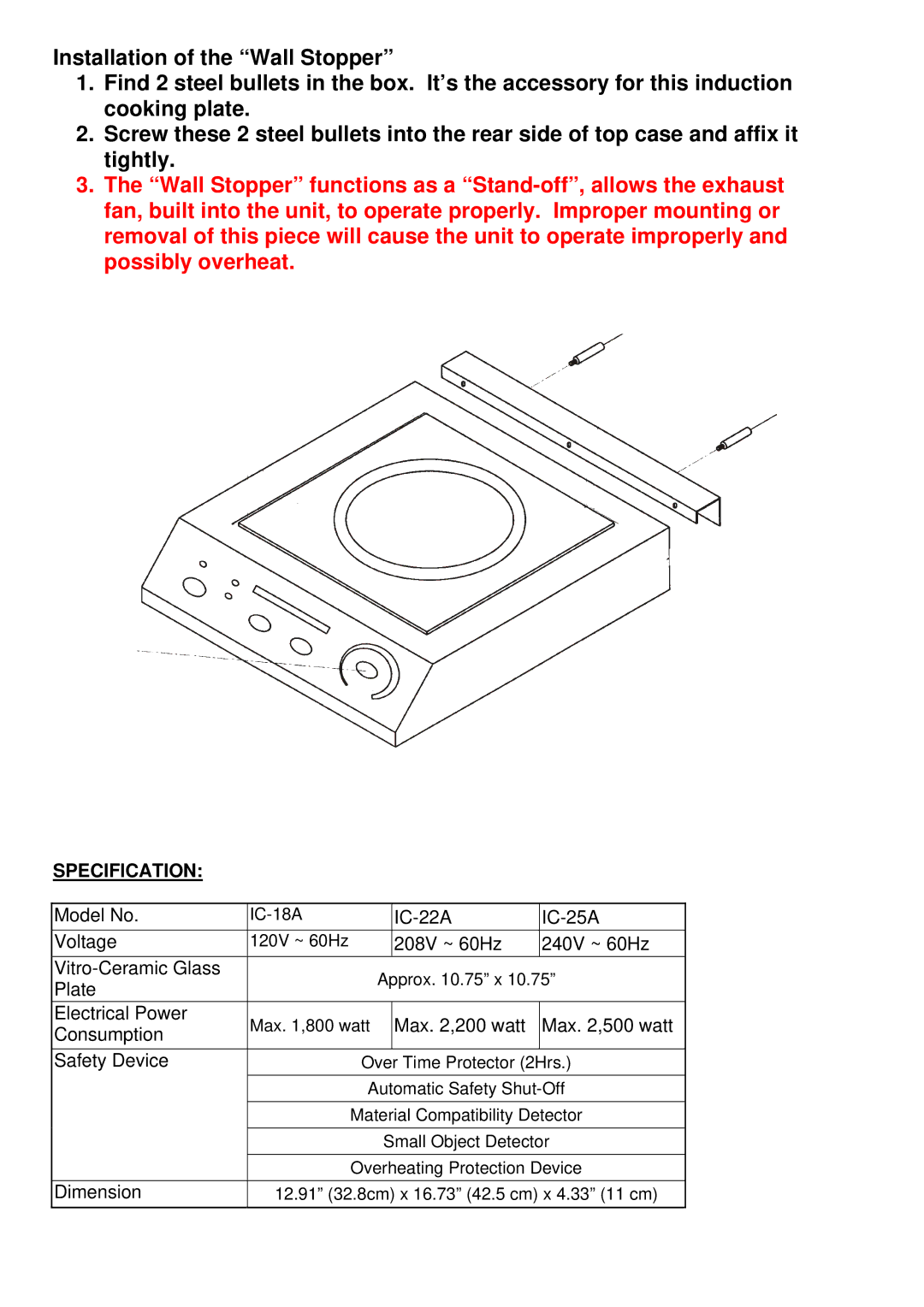
IC-25A, IC-22A, IC-18A specifications
The Cecilware IC-22A, IC-25A, and IC-18A are three remarkable models of coffee brewers that exemplify durability, efficiency, and superior brewing capabilities. Designed primarily for commercial environments, these models are widely used in restaurants, cafes, and other foodservice establishments where a continuous supply of quality coffee is essential.The IC-22A model is known for its ability to brew up to 22 gallons of coffee per hour, making it an excellent choice for high-demand settings. This brewer utilizes a modular design with a stainless steel construction, which ensures longevity and easy maintenance. Equipped with a powerful brew pump, the IC-22A offers consistent water pressure for optimal extraction, ensuring a rich and flavorful coffee. Its user-friendly controls and adjustable brew time further enhance the brewing process, allowing baristas to customize coffee to their specific taste profiles.
The IC-25A is another heavy-duty coffee brewer, designed for ultra-high capacity, brewing up to 25 gallons per hour. This model boasts a dual brewing system that enables simultaneous brewing of two different coffee types, catering to diverse customer preferences. The IC-25A is equipped with advanced temperature control technology to maintain precise brewing temperatures, further ensuring exceptional taste and aroma. Its built-in safety features prevent overheating and ensure consistent performance during peak hours.
The IC-18A model, while slightly smaller, still holds its ground with a brewing capacity of up to 18 gallons per hour. It features a sleek design combined with efficient technology that makes it perfect for medium-volume establishments. Like the other models, the IC-18A has a robust stainless steel construction that guarantees durability in busy environments. It also incorporates an easy-to-read digital display that provides precise brewing time and temperature monitoring, simplifying operations for staff.
All three models offer a range of technologies that enhance user experience, including an automatic shut-off feature to conserve energy and increase safety, as well as a convenient water level indicator for easy monitoring. The versatility of these brewers allows for the use of various coffee formats, and they are compatible with both ground coffee and coffee pods.
Overall, the Cecilware IC-22A, IC-25A, and IC-18A are exemplary machines that merge technology with practicality, delivering optimal performance and exquisite coffee flavor tailored to the needs of any busy coffee establishment.

